


This simple circuit automatically activates or deactivates an electronic device at the time of alarm preset in a clock. When the alarm rings, the tone burst generated at the terminal of the buzzer triggers the circuit and the relay energises or de-energises to switch on or switch off the load.
Digital Timer Circuit
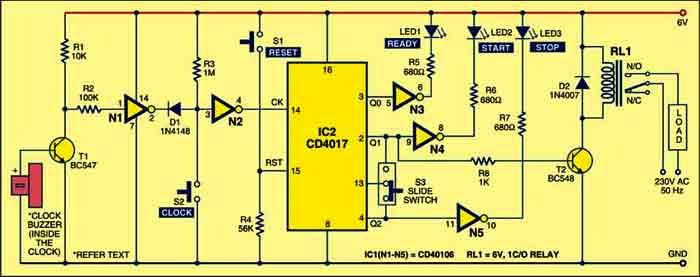
The circuit is built around ICs CD40106 (IC1) and CD4017 (IC2) and a few discrete components. IC1 is a hex Schmitt trigger, while IC2 is a decade counter. The circuit works off a regulated 6V power supply, while the alarm clock runs off its own 1.5V battery.
The tone burst generated at the piezo buzzer is tapped from its connection points. The positive terminal of the clock buzzer is connected to the base of transistor T1 and the negative terminal is connected to the ground of the circuit.

When the alarm clock sounds, the signal from the clock buzzer makes transistor T1 conduct. As a result, pin 1 of gate N1 goes low and it outputs high at pin 2. This low-to-high transition clocks the counter (IC2) at pin 14 through diode D1 and gate N2. In this way, IC2 advances by one at each clock produced due to the sounding alarm.
There are two situations where this circuit can be used:
- You want an appliance or gadget to switch on automatically at a preset time
- You switch on an appliance or gadget manually at a particular time and want it to switch off automatically at a preset time.
Circuit operation
Let us see how it works when you want your appliance to switch on at a preset time, say, 3 pm. Set the alarm on your clock to 3 pm and slide switch S3 towards Q1. When the alarm sounds at 3 pm, Q0 output of IC2 advances to Q1 and relay RL1 energises to connect the load (appliance) to mains power supply through its contacts. The load remains ‘on’ until you reset IC2 by momentarily pressing S1. At this time, you need to pause the alarm using pause switch off the clock.
Now suppose you manually start the load at 3 pm and want it to stop automatically at 6 pm. First, reset IC2 by momentarily pressing S1 and slide switch S3 towards Q2. Set the alarm on your clock to 6 pm. To start the load, press switch S2 momentarily at 3 pm. The Q0 output of IC2 advances to Q1 and relay RL1 energises to connect the load to mains power supply through its contacts. When the alarm sounds at 6 pm, Q1 output of IC2 advances to Q2 and relay RL1 de-energises to disconnect the load from mains power supply through its contacts. At this time, you need to pause the alarm using pause switch off the clock.
Reset the timer
When you press reset switch S1, LED1 glows to indicate that the circuit is ready to work. When you press start switch S2, LED2 glows to indicate start mode. Glowing of LED3 means that the counter has stopped counting and needs to be reset before use.
When the counter is in stop mode, Q2 output of IC2 remains high. As this pin is connected to the clock-enable input (pin 13) of IC2, the clock input is inhibited. In this condition, any tone burst signal arriving from the clock has no effect on IC2 and therefore the circuit remains in stop mode. You can now set the alarm time on the clock.
When the alarm clock sounds, the signal from the clock buzzer makes transistor T1 conduct. As a result, pin 1 of gate N1 goes low and it outputs high at pin 2. This low-to-high transition clocks the counter (IC2) at pin 14 through diode D1 and gate N2. In this way, IC2 advances by one at each clock produced due to the sounding alarm.
Circuit applications
There are two situations where this circuit can be used:
- You want an appliance or gadget to switch on automatically at a preset time
- You switch on an appliance or gadget manually at a particular time and want it to switch off automatically at a preset time.
Construction & testing
Assemble the circuit on a general-purpose PCB and enclose in a small cabinet. Connect the base of the transistor (T1) to the positive terminal of the alarm clock and negative terminal to the ground of the circuit. Put the alarm clock at a convenient place. If you do not want to use a 6V battery, replace it with a 6V adaptor to power the circuit. Mount the LEDs and the pushbutton on the front panel of the cabinet.
The project was first published in May 2010 and has recently been updated.