


Stroboscope is a device used to make a cyclically moving object appear slow-moving or stationary. This is realised by illuminating the object intermittently with short pulses of light. Stroboscope is used in the study of insect flight. It can also be used for experiments with simple pendulum, studying details of rapidly moving objects and strobo-animation.
Here is the circuit of a stroboscope that produces dual-coloured light pulses (refer Fig.1). The circuit uses red and green LEDs as light sources to illuminate the object. You can choose the frequency of the stroboscope’s light pulses from a wide range of 5 Hz to 5 kHz as desired. The range of frequency (5-50 Hz, 50-500 Hz, 500 Hz-5 kHz, etc) is selected through capacitors Ca (C2, C3 and C4), Cb (C5, C6 and C7) and Cc (C8, C9 and C10).
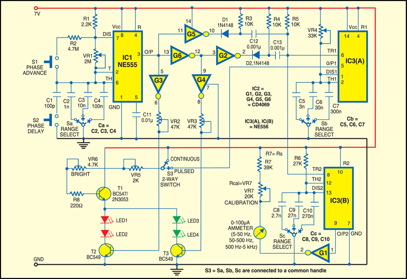
Smooth variation of the frequency range is achieved by varying VR1. The length of the light pulses (both red and green pulses are of equal duration) is adjusted by VR4. A flash of red and green light makes one cycle of the stroboscope. The frequency meter reads this frequency.
The circuit comprises a free-running oscillator formed by IC NE555 (IC1), IC CD4069 (IC2), dual-timer IC NE556 (IC3) and a few discrete components. The pulse output at pin 3 of NE555 triggers one-shot monostable IC3(A), which outputs a positive-going pulse that appears at the anodes of the LEDs (LED1 through LED4) through transistor T1.
However, gates G3 and G4 cause only one of the transistors T2 and T3 to turn on. So the positive-going pulse from monostable IC3 (A) causes either the red LEDs (LED1 and LED2) or the green LEDs (LED3 and LED4) to turn on, depending on the phase of the oscillator.
The astable multivibrator configured around IC1 is made to produce a symmetric square waveform by using the combination of low-value fixed resistor R1 (2.2-kilo-ohm) and high-value potmeter VR1 (2-mega-ohm).
One-shot monostable IC3 (B) configured as a frequency meter triggers along with IC3(A). Strobe-phase delay or advance facility introduces a shift in the stationary orientation either clockwise or anti-clockwise when S2 is pressed momentarily. The 100µA ammeter is calibrated to read the frequency from 5 Hz to 5 kHz.
Presets VR5 and VR6 are used to set the maximum brightness of the LEDs. Potmeter VR7 is used to calibrate the frequency scale on the ammeter. The supply voltage should be regulated (7.0V) and there should be no voltage drop across the circuit when the LEDs glow. Any voltage drop affects the meter readings.
Assemble the circuit on a general-purpose PCB and enclose in a suitable cabinet. Fix the LEDs on the top or front side of the cabinet such that the LEDs’ light falls on the moving object.
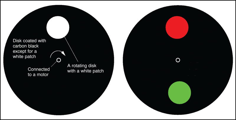
For testing, construct a paper disk with two white patches as shown in Fig. 2. Fit the disk onto a direct-current motor spindle.
Using switches S1 and S2, change the position of the patches in advance and delay motion, respectively. Pressing S1 slightly increases the frequency and pressing S2 slightly reduces the frequency. The change in frequency will make the patches to move in either clockwise or anti-clockwise direction.
Switch S3 provides a direct way to toggle between continuous and pulsed variable time periods. When switch S3 is thrown to continuous mode, the lights (LED1 through LED4) never go off—green and red LEDs glow alternately. For 50 per cent duty cycle of NE555, both red and green light go on and off alternately for the same duration. Use bright red and green LEDs for a good stroboscope output.
To measure the revolutions per minute (RPM) of the disk, tune the frequency using VR1 until stationary red and green patches are seen on the rotating disk. Next, note the reading of the ammeter to get revolutions per second (RPS) of the disk or motor. Multiply the result by 60 to get the RPM.
The stroboscope can be used to measure the RPM of a ceiling fan or table fan. For good visibility, make sure that the fan is clean and the light in the room switched off. Focus the red and green LED lights on the wings of the rotating fan. Vary VR1 until stationary red and green lights are seen on the wings of the rotating fan. Read the ammeter and divide the reading by 3 (for three wings of the fan) to get the rotation speed in RPS.