


 This circuit generates two different frequencies and mixes these to produce a balanced ringing tone, which can be used in burglar alarms or call bells.
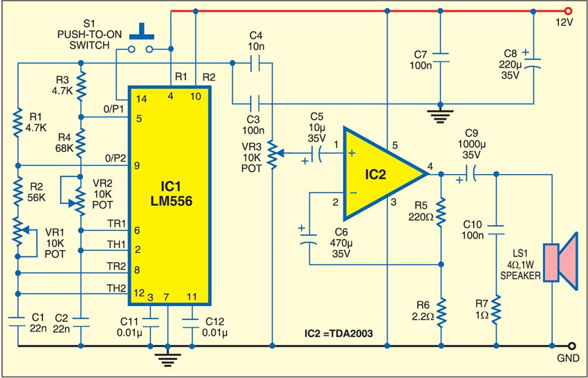
The circuit uses a dual-timer IC LM556 (IC1) and penta-watt audio power IC TDA2003 (IC2) (refer Fig. 1). Both the timers of LM556 are wired as astable oscillators to generate square waves. The first timer is configured to generate a 400Hz audible tone and the second timer for a 550Hz tone. The frequencies of both the oscillators are mixed and amplified by IC2. A higher frequency would result in shrill and unpleasant sound.
For better performance, the speaker should have a good-quality woofer with coil impedance of 4 ohms. Use a proper heat-sink for IC2. Adjust potmeters VR1 and VR2 to achieve a pleasant sound. Potmeter VR3 is used for volume control.

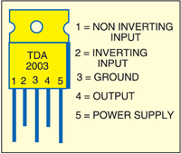
Assemble the circuit on a general-purpose PCB and enclose in a suitable cabinet. Refer Fig. 2 for pin configuration of TDA2003. Connect the switches at the front panel and the speaker at the back side of the cabinet.

Please post PCB layout of this circuit