If you want to test an audio amplifier, here is a compact fan-cooled dummy load that can be used to provide any of the three commonly needed load impedances (4 Ω, 6 Ω or 8 Ω), with power rating varying from 125 W to 250 W. Interestingly, this dummy load can be made using readily available and relativity low-cost parts.
If you ever need to check the performance of an audio amplifier, a resistive dummy load can be a very handy tool. For accurate Amplifier testing of aspects such as frequency performance, power output and signal-to-noise ratio, the ‘flat’ performance of a resistive dummy load is virtually essential as even the best speakers tend to have peaks and troughs in their impedance curve, which can distort your measurements.
In any case, you wouldn’t want to have speakers connected to an amplifier undergoing power output tests. Even if the speakers could cope with the continuous power output without damage, the resulting sound levels would be deafening.

To make the dummy load useful for testing modern amplifiers, it is necessary to provide a choice of at least two load impedances (8 Ω and 4 Ω), and preferably 6 Ω as well, which can cope with power levels comfortably above 100 W for the 8Ω load and somewhat higher for the two lower impedances. A small (80mm) computer-type ‘muffin ’cooling fan is used to help the resistor cope with dissipating high powers.

Circuit and working
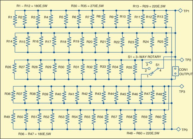
Fig. 2 shows the arrangement of resistor banks and Fig. 3 shows the complete circuit. The circuit is built around 60 resistors (R1 through R60). The load resistors are connected in three parallel groups. Two groups with 25 resistors each form two sets of 8Ω, 125W loads. The third group forms the load of 24 Ω, 50 W.
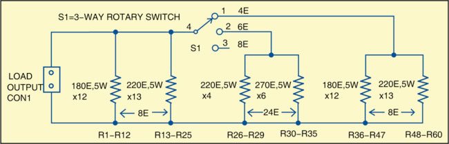
One of the 8Ω groups is connected permanently across output terminal CON1 and forms a basic 8Ω load, while the other two groups are switched in parallel with the existing 8Ω load by switch S1, whenever required, to provide either 6Ω or 4Ω load impedance.
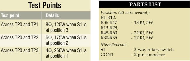
When switch S1 is at position 3, only the 8Ω group is connected across CON1 and forms the basic 8Ω load. When switch S1 is at position 1, 4 Ω is connected across the load output terminals. 6Ω load can be selected by placing switch S1 in position 2.
The accuracy of the actual impedance levels provided by the final dummy load is determined mainly by the within-tolerance variations of the actual resistors used. Switch S1 is a three-way rotary switch that is used to connect two sections in parallel for the required dummy load. As the switch is rated at 6 A per section, it should handle up to 12 A quite reliably.
Construction and testing
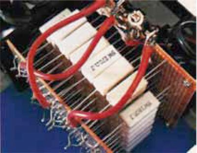
Since the dummy load can be constructed more easily using general-purpose PCBs, as shown in Fig. 1, so no PCB design is provided.
Assemble three sets of resistor banks using back-to-back general-purpose PCBs as shown in Fig. 1. The first set is built using resistors R1 through R25 for making a load of about 8 Ω. The second set is built with resistors R26 through R35 for making a dummy load of about 24 Ω. The third set is built using resistors R36 through R60 for making a dummy load of about 8 Ω.
Connect switch S1 and the loads as shown in Fig. 2. After proper assembly, insert the fan in such a way that it can easily dissipate the heat. For amplifier testing, use a multimeter to measure the resistance according to the test-point table.
The author is a regular contributor to EFY and has many articles published to his credit in India and abroad