


 Here is a simple circuit that can produce the effect of candle light in a normal electric bulb. A candle light, as we all know, resembles a randomly flickering light. So, the objective of this project activity is to produce a randomly flickering light effect in an electric bulb.
To achieve this, the entire circuit can be divided into three parts. The first part comprises IC1 (555), IC2 (74LS164), IC3 (74LS86), IC4 (74LS00) and the associated components. These generate a randomly changing train of pulses.
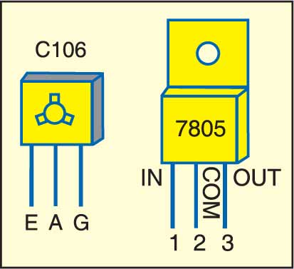
The second part of the circuit consists of SCR1 (C106), an electric bulb connected between anode of SCR1 and mains live wire, and gate trigger circuit components. It is basically half-wave AC power being supplied to the electric bulb.
The third part is the power supply circuit to generate regulated 5V DC from 230V AC for random signal generator.

It comprisesastep down transformer (X1), full-wave rectifier (diodes D3 and D4), filter capacitor (C9), followed by a regulator (IC5).The random signal generator of the circuit is built around an 8-bit serial in/parallel out shift register (IC2). Different outputs of the shift register IC pass through a set of logic gates (N1 through N5) and final output appearing at pin 6 of gate N5 is fed back to the inputs of pins 1 and 2 of IC2. The clock signal appears at pin 8 of IC2, which is clocked by an astable multivibrator configured around timer (IC1). The clock frequency can be set using preset VR1 and VR2. It can be set around 100 Hz to provide better flickering effect in the bulb.
The random signal triggers the gate of SCR1. The electric bulb gets AC power only for the period for which SCR1 is fired. SCR1 is fired only during the positive half cycles. Conduction of SCR1 depends upon the gate triggering pin 3 of IC2, which is random. Thus, we see a flickering effect in the light output.
Assemble the circuit on a general-purpose PCB and enclose it in a suitable case. Fix bulb and neon bulb on the front side of the cabinet. Also, connect a power cable for giving AC mains supply to the circuit for operation. The circuit is ready to use.
Warning. Since the circuit uses 230V AC, care must be taken to avoid electric shock.

Nice idea and circuit, but… Isn’t D4 round the wrong way? Are two VRs really necessary? If you need to change the mark/space ratio, use one VR (PR?) to do this and the other to alter the freq. The 555 could be eliminated because there is a spare Xor gate which could be made to oscillate (tie one input to V+ and use R/C from output to other input). Even if the 555 is kept, a cap of around 100microF should be used across it because of the (relatively) high current use of the 555 (that’s why I don’t like them). There are two unused gates on the 74LS00 – those inputs should be tied to a supply rail. Using all CMOS devices would use even less current. Lastly, there are already “flickering” mains lamps available!