


 It would be cool to build an electronic tone generator system yourself. Described here is a small tone generator based on pulse-width modulation (PWM) concept in which a piezo buzzer generates multiple tones with the help of Arduino software programming.
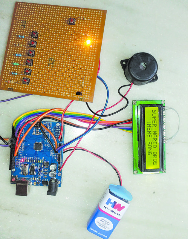
You can see how the device works, including the menu of preset musical tones, in the author’s prototype shown in Fig. 1. There are five musical tones already programmed in this project. Technically, tones four and five in this project are the same, which are left to readers to create better ones.
Writing a musical code was not the goal of the project. Basic coding for main loops and individual tone loops is easy to adapt to your own ideas, so feel free to change the code as per your requirement.

Tone Generator Circuit and Working
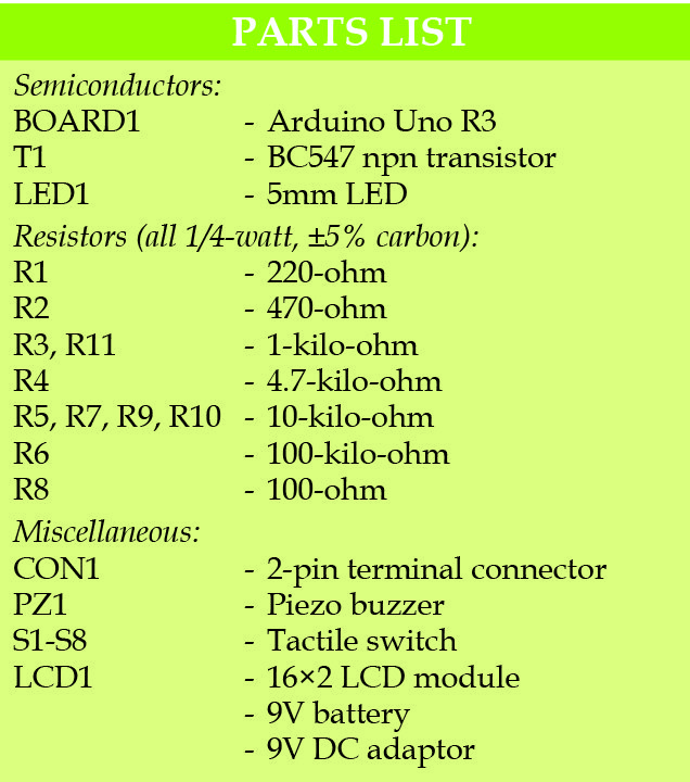
Circuit diagram of the electronic tone generator is shown in Fig. 2. It is based on Arduino Uno board (BOARD1), liquid crystal display (LCD1), transistor BC547 (T1), a buzzer (PZ1) and a few other components.
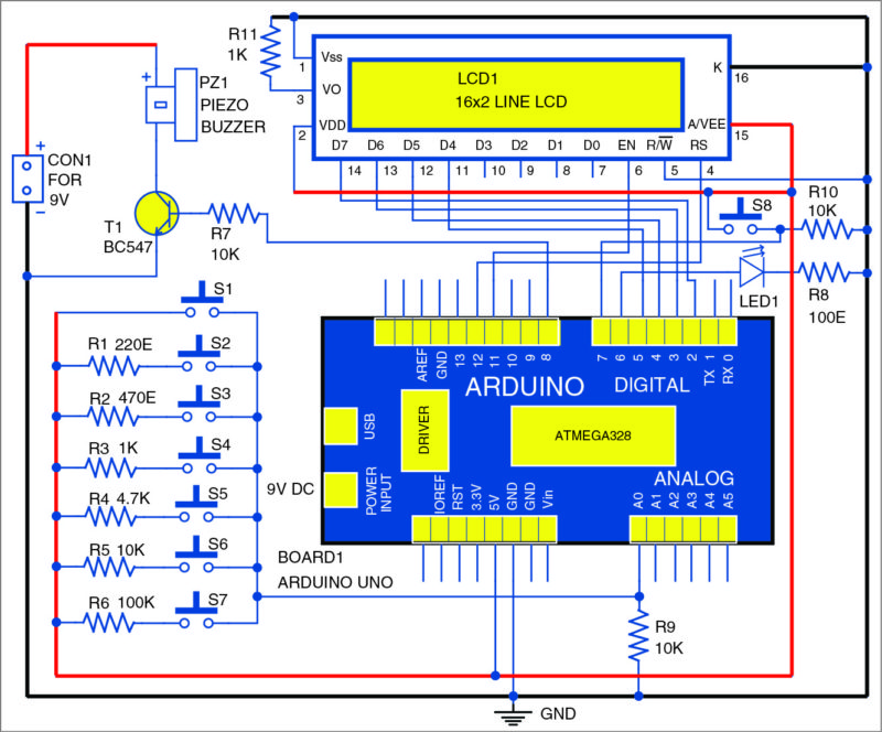
Tone key switches (S1 through S7) are connected using a resistor ladder. The resistors (R1 through R6) are placed in a sequential order, connecting each switch to 5V power supply. Resistor values (in ohms) used are 100k, 10k, 4.7k, 1k, 470-ohm and 220-ohm.

S1 is directly connected to 5V power supply. One terminal of switch S2 is connected to 5V supply through R1 and the other terminal to pin A0 of Board1. Switches S3 through S7 are also connected to analogue pin A0 of Arduino Uno board in a similar manner.
The Arduino program (tone_generator.ino) defines the musical notes and frequencies associated with each tone key. Change the frequency values or add additional switches to fully customise your project.
LCD screen
Connect the LCD1 pins according to the circuit diagram shown in Fig. 2. Resistor R11 connected at pin 3 of LCD1 is used as the contrast control of the screen. Pin 15 of LCD1 is connected to 5V power supply and pin 16 is connected to ground for backlight on the LCD screen. LCD1 is configured in 4-bit mode. Its pins D4, D5, D6 and D7, register select (RS) and enable (EN) are connected to pins 5, 4, 3, 2, 12 and 11, respectively, of the Arduino Uno R3 board. Read/write (R/W) pin is connected to ground.
Connect one terminal of menu switch S8 to 5V and the other terminal to ground through R10. Also, connect it to pin 7 of the Arduino.
Glowing of LED1 indicates that you are in Menu mode and the tone keys have been disabled. LED1 turns on once S8 is pressed. Connect the anode (positive) of LED1 to pin 6 of Arduino Uno and cathode to ground through R8.
To integrate the piezo buzzer (PZ1) through transistor T1, connect the base of the transistor to Arduino’s pin 8 through R7. Connect piezo buzzer’s negative terminal to the collector of T1 and positive terminal to 9V battery.
Software
Circuit operation is done using the software program (tone_generator.ino) loaded into the internal memory of Arduino Uno R3. The program implements all required functionalities including handling user inputs with the help of switching interface. The program is written in Arduino programming language. Arduino IDE 1.6.4 is used to compile and upload the program (called sketch).
The sketch begins by importing LiquidCrystal.h and MyTones.h libraries, so you can reference various items from these later on in the code.
Next, the code starts by defining a name for S8, inputs versus outputs, and setting the frequency values for each of the seven pushbutton keys (switches S1 through S7).
A new tab is created for each individual tone in an effort to keep the code organised and easier to understand. If you wish to delete or add more tones, make sure to change the code in the main program/sketch as well.
Main loop
The program begins with the LED1 turned off, and all tone keys (S1-S7) active. Once the loop detects that S8 has been pressed, it disables S1 through S7, and turns the LED1 on to indicate that you are in Menu mode.
Accessing the menu
Press Menu button to cycle through the present tones and press any key (S1 through S7) to start playing the tone displayed on the LCD1 screen.
The LCD1 screen will show the tone that is currently playing and then return to the same point in the menu once the tone has finished playing. From there, you can either replay or continue to play next tone available in the list. Double-click S8 to restart the menu from the beginning.
Here, we have created five musical tones: Super Mario Bros Theme song, Super Mario Bros Underworld song, Jeopardy Theme song, and the fourth and fifth are same modified version of Jeopardy Theme song generated for you to modify. To return to tone keys, cycle through the remaining tones in the menu. Once LCD1 screen is blank and LED1 is off, press each key (S1 to S7) to generate unique beep tones.
Download source code
Construction and Testing
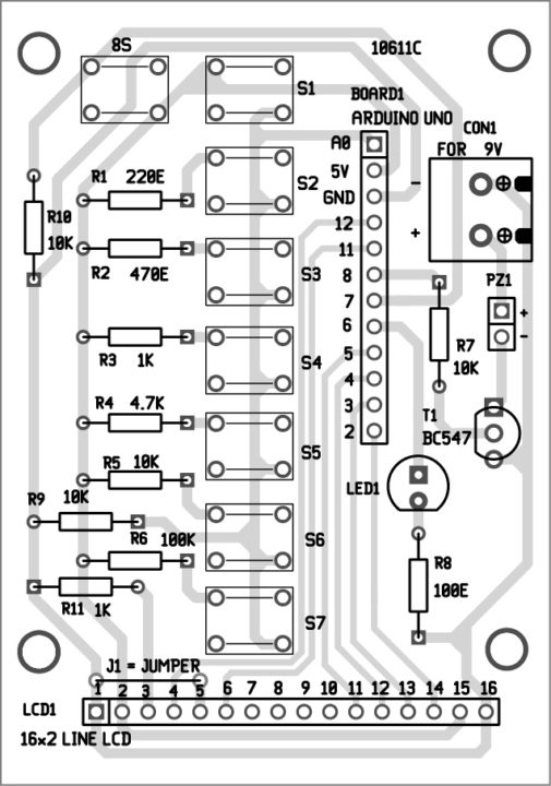
An actual-size, single-side PCB for the electronic tone generator is shown in Fig. 3 and its components layout in Fig. 4. After assembling the circuit, enclose it in a suitable box.
Fix CON1, LED1 and S1 through S8 on the front panel of the box. Connect the 9V using a 9V adaptor to Arduino Uno board and 9V battery for PZ1.
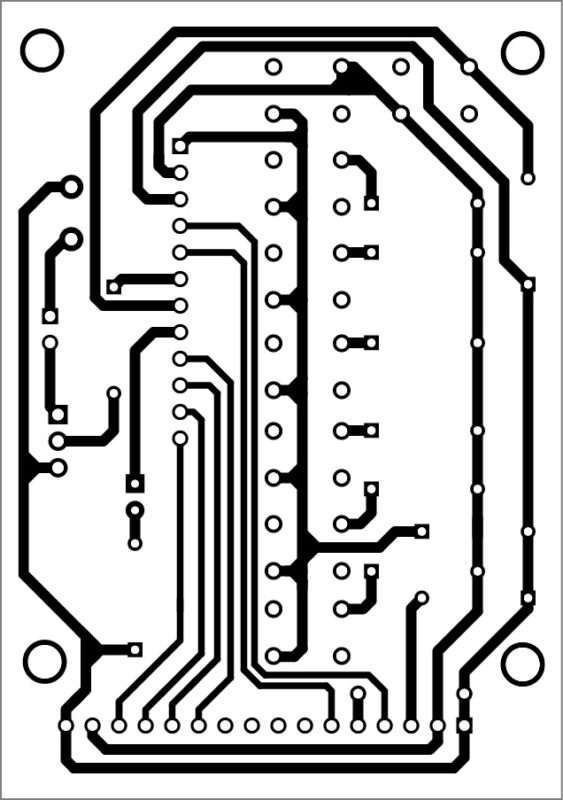
Download PCB and component layout PDFs: click here
Testing Procedure
After assembling the circuit, upload the program into Arduino Uno board. Connect 9V adaptor to Arduino Uno. LCD1 is blank and LED1 remains off. Tone switches produce individual tones when each switch is pressed momentarily. Press S8 momentarily and tone switches will get disabled.
When you press S8 again, LCD1 shows the message: “Which song would you like to play?” When you press any tone key, the first tone starts playing.
On further pressing S8, the next tone will be displayed on the LCD1. When you press any tone key again, the second tone starts playing. Thereafter, repeat the same process till the last tone is played. Press S8 again and the LCD1 will be blank.