


 Aburst water-supply hose of the washing machine, a bathroom tap that you forgot to close, or a broken aquarium wall may turn your house into a pond. You can avoid this mess by using an electronic water alarm that warns you of the water leakage as soon as possible.
The acoustic water alarm circuit presented here takes advantage of the fact that the tap water is always slightly contaminated (or has salts and minerals) and thus conducts electricity to a certain extent. It is built around IC LMC555 (IC1), which is a CMOS version of the bipolar 555 timer chip. IC1 is followed by a complementary pair of emitter followers (T1 and T2) to drive a standard 8-ohm speaker (LS1). Power is supplied by a compact 9V PP3 battery.
Power is applied when power switch S1 is closed. The reset input (pin 4) of IC1 is held low by resistor R1 (2.2-kilo-ohm). The astable oscillator wired around IC1 is in disabled mode. When probes P1 and P2 become wet, these conduct to reverse the state of IC1’s reset terminal. As a result, the astable multivibrator starts oscillating at a frequency determined by resistor R2 and capacitor C3. The output of IC1 drives the complementary pair of transistors T1 and T2.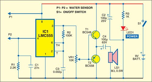

Although this combination causes significant crossover distortion, it doesn’t have any adverse effect on the square-wave audio signal processing. A 10-kilo-ohm potentiometer (VRI) is inserted between output pin 3 of IC1 and the bases of transistors T1 and T2 for volume control.
The probes can be made using two suitable copper needles or small pieces of circuit board with the copper surface coated with solder. Fit these at the lowest point where water will accumulate. After construction, place the alarm circuit well away from the point of possible leakage. Use a pair of thin twisted flexible wires to connect the probes to the circuit.
Capacitor C1 connected across IC1 input (pin 4 and GND) keeps the alarm circuit from responding to stray electrostatic fields. Similarly, twisting the wires together makes the relatively long connection between the probes and the circuit less sensitive to false alarms due to external electromagnetic interference. Finally, if you want to lower the probe sensitivity, reduce the value of grounding resistor R1.
