


 This 7-segment display dice circuit has been realized using an astable oscillator circuit followed by a counter, display driver and a display. Here we have used a timer NE555 as an astable oscillator with a frequency of about 100 Hz. Decade counter IC CD4026 or CD4033 (whichever available) can be used as counter-cum-display driver. When using CD4026, pin 14 (cascading output) is to be left unused (open), but in case of CD4033, pin 14 serves as lamp test pin and the same is to be grounded.
7-segment display dice circuit
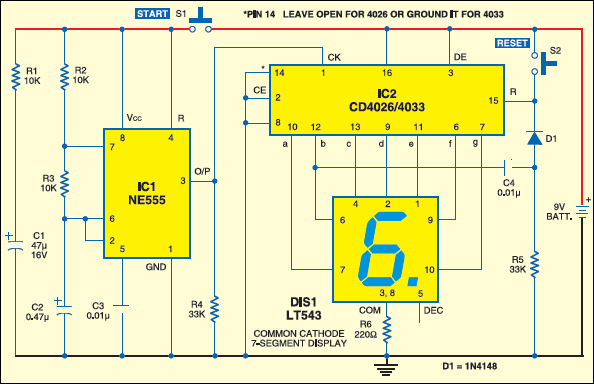
The circuit uses only a handful of components. Its power consumption is also quite low because of use of CMOS ICs, and hence it is well suited for battery operation. In this circuit two tactile switches S1 and S2 have been provided. While switch S2 is used for initial resetting of the display to ‘0’, depression of S1 simulates throwing of the dice by a player.
When battery is connected to the circuit, the counter and display section around IC2 (CD4026/4033) is energised and the display would normally show ‘0’, as no clock input is available. Should the display show any other decimal digit, you may press re-set switch S2 so that display shows ‘0’ .

To simulate throwing of dice, the player has to press switch S1, briefly. This extends the supply to the astable oscillator configured around IC1 as well as capacitor C1 (through resistor R1), which charges to the battery voltage.
Thus even after switch S1 is released, the astable circuit around IC1 keeps producing the clock until capacitor C1 discharges sufficiently. Thus for duration of depression of switch S1 and discharge of capacitor C1 thereafter, clock pulses are produced by IC1 and applied to clock pin 1 of counter IC2, whose count advances at a frequency of 100 Hz until C1 discharges sufficiently to deactivate IC1.

Circuit operation
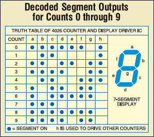
When the oscillations from IC1 stop, the last (random) count in counter IC2 can be viewed on the 7-segment display. This count would normally lie between 0 and 6, since at the leading edge of every 7th clock pulse, the counter is reset to zero. This is achieved as follows.
Observe the behavior of ‘b’ segment output in the Table. On reset, at count 0 until count 4, the segment ‘b’ output is high. At count 5 it changes to low level and remains so during count 6. However, at start of count 7, the output goes from low to high state.
A differentiated sharp high pulse through C-R combination of C4-R5 is applied to reset pin 15 of IC2 to reset the output to ‘0’ for a fraction of a pulse period (which is not visible on the 7-segment display). Thus, if the clock stops at seventh count, the display will read zero.
There is a probability of one chance in seven that display would show ‘0.’ In such a situation, the concerned player is given another chance until the display is non-zero.
Note. Although it is quite feasible to inhibit display of ‘0’ and advance the counter by ‘1’, the same makes the circuit some what complex and therefore such a modification has not been attempted.
Feel interested? Check out other electronics projects.
At the place of Ic 2, instead of 4026/4033 can i use ic 4017 ?
4017 not for 7-segment… It can be use on normal LED dice…
Can u give me the uses and applications of 7segment display electronic dice please?
Ludo or any dice game…
What should i change in this circuit to bound it in 0 to 6?
Can i change the 0.47uf with a difference capacitance?
Yes, you can, but the clock pulse will change accordingly.
Hi. Can I make the 7 segment slow down when the button is released and then show the number and not stop abruptly.
Great project.
I have now sorted this out.
CAN YOU HELP ME !!
please Mail me or text me on instagram!!
i really need help
We have emailed you.