In the output stages of most broadcast receivers and some amplifiers, there is a limit up to which maximum power can be developed without distortion. In the widely accepted output circuit, two output transistors are connected in series between the positive and ground and biasing is adjusted so that each transistor gets half the supply voltage. The circuit presented here is a simple audio amplifier for a personal stereo system. In this, supply voltage to each transistor can be enhanced to produce a larger output. The audio driver transformer drives the transistors adequately.
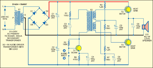
A 9V-0-9V, 300mA transformer has been used in the set-up. Out of the four diodes (D1through D4), two are used for developing the positive voltage rail (+9V) and the other two are used for developing the negative voltage rail (–9V). In the pushpull amplifier, each transistor (T2 or T3) gets double the voltage when activated.
Connect the low audio signal from the stereo system at input terminals A and B of the audio amplifier and provide mains AC to activate the circuit. During the first half cycle of an AF cycle, transistor T2 conducts and the current flows from positive rail to ground rail (centre tap of transformer X1) via the loudspeaker coil (connected between the emitter of transistor T2 and ground) in one direction. While in the second half cycle, transistor T3 conducts and the current flows from ground rail to negative rail via the loudspeaker coil (connected between ground and the collector of transistor T3) in a direction opposite to the previous flow.
Transistors T2 and T3 of the pushpull audio amplifier should be matched correctly. If these transistors get heated, change the bleeding resistor pairs (R3 and R4 for transistor T2 and R5 and R7 for transistor T3) so that the acceptable output without overheating is obtainedYou can also replace these transistors with another pair of suitable high-power transistors.

For driving transistors T2 and T3, a 9V audio driver transformer having six leads is used. It is readily available in the market and reasonably matches the output and input impedances of the preceeding and succeeding stages.
To test the quality of the audio output, connect the stereo’s outputs to the respective terminals A and B. Now increase the volume level of the stereo slowly. If you get a high-level, high-quality sound across loudspeaker L1, the amplifier is working well. If the sound quality is not good, decrease the volume level until the audio amplifier gives good results.
Note. that this audio amplifier works well for low-level audio signals.