


 This auto turn-off battery charger for series-connected 4-cell AA batteries automatically disconnects from mains to stop charging when the batteries are fully charged. It can be used to charge partially discharged cells as well. The circuit is simple and can be divided into AC-to-DC converter, relay driver and charging sections.
Circuit Description
In the AC-to-DC converter section, transformer X1 steps down mains 230V AC to 9V AC at 750 mA, which is rectified by a full-wave rectifier comprising diodes D1 through D4 and filtered by capacitor C1. Regulator IC LM317 (IC1) provides the required 12V DC charging voltage. When you press switch S1 momentarily, the charger starts operating and the power-on LED1 glows to indicate that the charger is ‘on.’
The relay driver section uses pnp transistors T1, T2 and T3 (each BC558) to energize electromagnetic relay RL1. Relay RL1 is connected to the collector of transistor T1. Transistor T1 is driven by pnp transistor T2, which, in turn, is driven by pnp transistor T3. Resistor R4 (10-ohm, 0.5W) is connected between the emitter and base of transistor T3.

When a current of over 65 mA flows through the 12V line, it causes a voltage drop of about 650 mV across resistor R4 to drive transistor T3 and cut off transistor T2. This in turn, turns transistor T1 ‘on’ to energize relay RL1. Now even if the push button is released, mains is still available to the primary of the transformer through its normally open (N/O) contacts.
Auto turn-off battery charger circuit
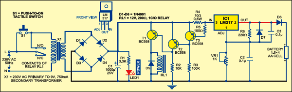
In the charging section, regulator IC1 is biased to give about 7.35V. Preset VR1 is used for adjusting the bias voltage. Diode D6 connected between the output of IC1 and battery limits the output voltage to about 6.7V, which is used for charging the battery.
Pushing switch S1 latches relay RL1 and the battery cells start charging. As the voltage per cell increases beyond 1.3V, the voltage drop across resistor R4 starts decreasing. When it falls below 650 mV, transistor T3 cuts off to drive transistor T2 and, in turn, cuts off transistor T3. As a result, relay RL1 de-energizes to cut off the charger and red LED1 turns off.
You may determine the charging voltage depending on the NiCd cell specifications by the manufacturer. Here, we’ve set the charging voltage at 7.35 V for four 1.5 V cells. Nowadays, 700 mAH cells are available in the market, which can be charged at 70 mA for 10 hours. The open-circuit voltage is about 1.3V.
The shut-off voltage point is determined by charging the four cells fully (at 70 mA for 14 hours). After measuring the output voltage, add the diode drop (about 0.65V) and bias LM317 accordingly.
More interesting projects available here.
Comment:sir can we use this to stop the over charging of normal smart phone plz reply soon sir u r reply matters me a lot
Can I make a version of this that uses a usb charger? I need to know for a project for my robotics class.
who invented this type of battery charger
If you have any specific query, please mention in detail
I need a pdf file for this project
thanks for this circuit sir if i want to charge 4 batteries (parallel connected ) li-ion battery what changes need to be done in this circuit. for my project i need to apply an voltage of max 5V to the batteries and current flow should be 2A.
can i use this for my phone
But how it will turn off and when how the circuit will understand that the battery is full or not .Or the circuit is time base that means when charger on it will be on fir some specific time?
do you have a pdf file of this project?
i need 12 v lithium iron battery charger circuit