


This bell-cum-light controller circuit is equipped with four switches labelled S1 through S4. While S4 is the mains ‘on’/‘off’ toggle switch for powering the timer circuit for lighting up a bulb for a specific duration (mainly during night), the functions and placement of the other three switches (which are push switches) follow.
Light controller circuit
Switch S1 (labelled ‘call-bell and timer-on’) is located at the outer entry gate of the house for use by a visitor. This switch activates bell circuit for as long as the switch is kept pressed. On its release, a timer is initialized, which, in turn, switches on a bulb to light up the path between the outer gate and the house door for a specific duration (3 minutes). Switch S2 (labelled ‘timer on’) is situated inside the house for use by the inhabitants for activating the above-mentioned timer for switching on the light for three minutes from inside the house. S2 is meant to be used during darkness with S4 ‘on.’
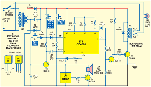
Like S1, switch S3 (labelled ‘callbell’) is located outside the entry gate. It is meant to be used during day, when mains switch S4 is ‘off.’ When switch S3 is pressed, it activates only the bell circuit for as long as the switch is kept pressed. Since the bell circuit is powered by a 3V battery, this circuit can be activated even if mains switch is off.

With switch S4 ‘on,’ the supply to bulb B1 is routed via N/O contacts of relay RL1. Simultaneously, the AC mains stepped down by transformer X1 is rectified by diodes D1 and D2 followed by filter capacitor C1. The DC supply thus becomes available for timer circuit comprising CD4060 (IC1) and relay driver circuit comprising transistors T1 and T2.
IC1 is a 14-stage binary counter and oscillator IC. In its quiescent state, the Q13 output (pin 3) is high, which results in conduction of transistor T1 to cut off transistor T2. Thus the relay is in de-energised state and the bulb is off.’
When the master reset is activated by pressing of switch S1 and/or S2, all the output pins of IC1 including Q13 output go low. Thus transistor T1 is cut off, while T2 conducts to energise relay RL1 as also the bulb. Once S1 and S2 are released, the timer starts counting.
Circuit operation
Pressing of switch S1 additionally results in forward biasing of transistor T3, which conducts to extend 3V battery supply to melody generator UM66 (IC2). The output of the melody generator drives transistor T3 to output the tune via loudspeaker LS1.
Thus, when a visitor presses switchS1 at the gate, the calling bell sounds and the timer resets. The Q13 output of IC1 goes low to cut off transistor T1. Transistor T2 conducts to energise the relay and turn the light ‘on.’
When switch S1 is released, the timer starts counting. After three minutes (determined by resistor R4 (100-kilo-ohm) and capacitor C3 (0.1μF), the Q13 output goes high, i.e., transistor T1 conducts and T2 cuts off. The relay de-energises to turn the light ‘off.’
Since diode D5 is connected from Q13 to clock input terminal (pin 11), the terminal is always high when Q13 is high, disabling the counting of IC1. So the state is latched until the next resetting takes place. ‘On’ time period can be varied according to the distance between the gate and the house. It is
decided by the values of resistor R4 and capacitor C3 as follows:
‘On’ period = 300xR4xC3 minutes
The light controller circuit will work at night, provided mains switch S4 is ‘on.’ During night, only switches S1 and S2 will be used, while switch S3 is used in the day for the calling bell only.
The article was first published in September 2006 and has recently been updated.
