 Here is a simple call bell circuit that displays a welcome message when somebody presses the call bell switch momentarily. The alphanumeric display can be fitted near the call bell switch.
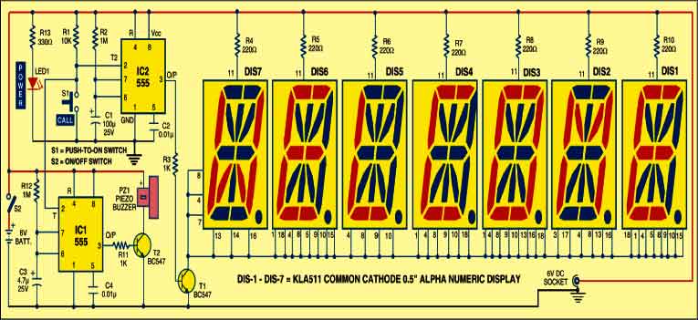
The circuit is built around two 555 ICs (IC1 and IC2), seven KLA511 common-anode alphanumeric displays (DIS1 through DIS7) and a few discrete components. For easy understanding, the entire circuit can be divided into two sections: controller and display. The controller section is built around IC1 and IC2, while the display section is built around alphanumeric displays DIS1 through DIS7).
As shown in the circuit, both IC1 and IC2 are wired as monostable multivibrators having time periods of around 5 seconds and 2 minutes, respectively. You can change the time period of IC1 by changing the values of resistor R12 and capacitor C3. Similarly, the time period of IC2 can be changed by changing the values of resistor R2 and capacitor C1. Alphanumeric displays DIS1 through DIS7 are wired such that they show ‘WELCOME’ when the output of IC2 goes high.

Working of the circuit is simple. First, power-on the circuit using switch S2. LED1 glows to indicate presence of power supply in the circuit. Now if you press call bell switch S1 momentarily, it triggers both the timers (IC1 and IC2) simultaneously. IC1 produces a high output at its pin 3 for about five seconds. transistor T2 conducts and piezobuzzer PZ1 sounds for about five seconds indicating that there is somebody at the door. At the same time, IC2 too produces a high output at its pin 3 for about two minutes. Transistor T1 conducts to enable the alphanumeric displays. The word ‘WELCOME’ is displayed for about two minutes as DIS1 through DIS7 ground via transistor T1. If switch S1 is pressed again within these two minutes, piezobuzzer PZ1 again sounds for five seconds and the display continues to show ‘WELCOME’.
Assemble the complete circuit on a general-purpose PCB and house in a small cabinet with call bell switch S1 and LED1 mounted on the front panel. At the rear side of the cabinet, connect a DC socket for the adaptor. Install the complete unit (along with the display) at the entrance of your house. Connect the 6V battery or 6V adaptor for powering the circuit. Configure switch 2 (used to enable/disable the call bell) in a switch board at a suitable location inside your house. If you don’tuse a battery, connect the power adaptor to the DC socket on the rear of the cabinet. Close switch S2 only when you want to activate the circuit with battery. Otherwise, keep it open when the 6V adaptor is in use.
EFY note. 1. To avoid any shorting during rain, waterproof the entire circuit assembly including alphanumeric displays (installed at the entrance) by covering it properly.
2. The complete kit for this circuit is available with EFY associates kits’n’spares.