


 Here’s a clap switch free from false triggering. To turn on/off any appliance, you just have to clap twice. The circuit changes its output state only when you clap twice within the set time period. Here, you’ve to clap within 3 seconds.
The clap sound sensed by condenser microphone is amplified by transistor T1. The amplified signal provides negative pulse to pin 2 of IC1 and IC2, triggering both the ICs. IC1, commonly used as a timer, is wired here as a monostable multivibrator. Trigging of IC1 causes pin 3 to go high and it remains high for a certain time period C3. This ‘on’ time (T) of IC1 can be calculated using the following relationship:
T=1.1R7.C3 seconds
where R7 is in ohms and C3 in microfarads. On first clap, output pin 3 of IC1 goes high and remains in this standby position for the preset time. Also, LED1 glows for this period The output of IC1 provides supply voltage to IC2 at its pins 8 and 4. Now IC2 is ready to receive the triggering signal. Resistor R10 and capacitor C7 connected to pin 4 of IC2 prevent false triggering when IC1 provides the supply voltage to IC2 at first clap.
On second clap, a negative pulse triggers IC2 and its output pin 3 goes high for a time period depending on R9 and C5. This provides a positive pulse at clock pin 14 of decade counter IC 4017 (IC3). Decade counter IC3 is wired here as a bistable.
Each pulse applied at clock pin 14 changes the output state at pin 2 (Q1) of IC3 because Q2 is connected to reset pin 15. The high output at pin 2 drives transistor T2 and also energises relay RL1. LED2 indicates activation of relay RL1 and on/off status of the appliance. A free-wheeling diode (D1) prevents damage of T2 when relay de-energises.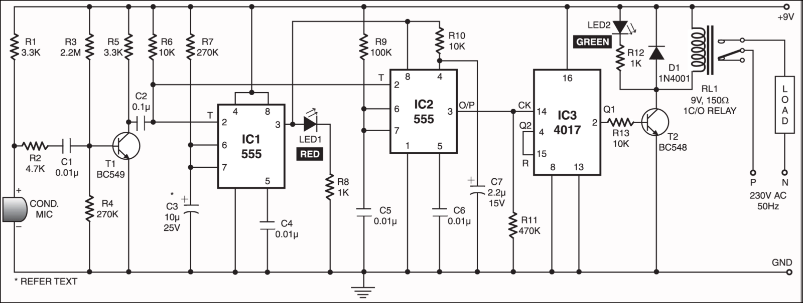
Plzz provide layout for thus clap switch circuit as soon as possible
Plzz provide layout for thus clap switch circuit as soon as possible
PCB layout is not available for this circuit, sorry.
Author is not mentioned of this article.
Thank you for your comment, we have updated the article.
Hello. I’m making this project. I started writing the schematic with kicad6.0. When I run the electrical rules check, the program signals me an error on pin 8 of the second 555. It tells me that it is not connected to the power. Is it possible that there is an error in the published schematic? Thank you