


In the evening, with the day’s work over, your office is locked and you are about to leave for home. Suddenly, you notice that some of the lights in your office are still on, which you can see from the factory gate. You open the browser in your laptop, do authentication, give a command, and all the lights in your office are switched off. You return home peacefully.


Take another case. You have gone somewhere and realise that you will not be returning to your office for quite some time. So you go to a nearby computer, open the browser, check the temperature in your office, press some keys on the computer and the AC in your office gets switched off. You can do all this with the help of Raspberry Pi, using WebIOPi software.
WebIOPi
WebIOPi is browser-based software through which the above-mentioned tasks can be done easily yet economically. The latest WebIOPi version 0.0.6 is available at:
http://code.google.com/p/webiopi/downloads/detail?name=WebIOPi-0.6.0.tar.gz&can=2&q=
Download it with ‘wget’ command or directly from the browser. Extract the tarball file in a directory using the command (also refer Fig. 1):
[stextbox id=”grey”]$ tar zxvf WebIOPi-0.6.0.tar.gz[/stextbox]
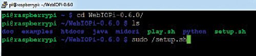
Now use ‘cd’ command to go to the extracted directory and run the following command (also refer Fig. 2):
[stextbox id=”grey”]$ sudo ./setup.sh[/stextbox]
WebIOPi will be installed in your Raspberry Pi. To start WebIOPi, run the following command (also refer Fig. 3):
[stextbox id=”grey”]$ sudo /etc/init.d/webiopi start[/stextbox]
This will not make WebIOPi start automatically at every boot. To start it automatically at the boot itself, give the command (also refer Fig. 4):
[stextbox id=”grey”]$ sudo update-rc.d webiopi defaults[/stextbox]
Accessing Raspberry Pi’s GPIOs
The WebIOPi is essentially an Apache webserver framework with facilities of Raspberry Pi GPIOs. If you already have Apache installed in your Raspberry Pi, just go ahead and WebIOPi will manage itself accordingly. If you do not have Apache, you can install it with the command:
[stextbox id=”grey”]$ sudo apt-get install apache2[/stextbox]
Once WebIOPi is installed, go to the browser window of your computer and open the link:
[stextbox id=”grey”]http://your-raspi-
ip-address:8000/
webiopi[/stextbox]
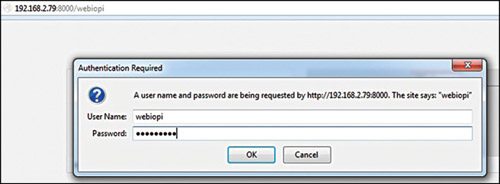
It will ask for a login and password, which you can change later. But for the time being type webiopi and raspberry as login and password, respectively, as shown in Fig. 5.
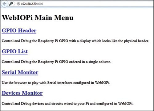
You will see the WebIOPi main menu, as shown in Fig. 6.

Click on the GPIO Header link and you will see the GPIO header pins along with the pin functions, as shown in Fig. 7. The ‘IN’ means the corresponding pin can be used as input. Double click on ‘IN’ box; the caption will change to ‘OUT.’ Now, the pin can be used as output pin.
Also Read:Interesting Electronic Projects
Controlling devices
Make all the eight pins as OUT, then connect a few LEDs on the corresponding pins on the Raspberry Pi board. Click on each pin, say pin 13 (GPIO 27) to begin with, on the browser screen; it will change from black to orange and the corresponding LED will glow.
Connect all the GPIO pins to the inputs of a Darlington IC ULN2003 and you will be able to control relays connected to the outputs of the IC. The relays, in turn, will be able to switch ACs, fans, lights, curtains, etc on and off. As long as you can access this page with LAN or any other wireless network, you will be able to control the GPIO pins and the devices attached to them.
Similarly, click on ‘OUT’ and it will change to ‘IN’ button, indicating that the port has changed from an output port to an input port.
Interface temperature sensor
DS18B20 digital temperature sensor can sense temperature from -10 to 85 degree celsious. The sensor looks like a small transistor with its three legs, as shown in Fig. 8.
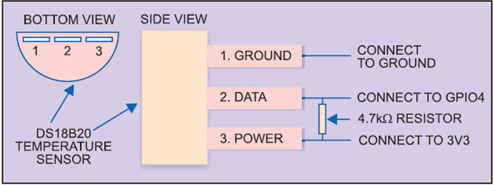


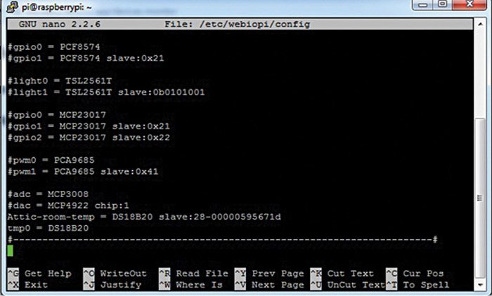

Fig. 8 also shows how to connect the GPIO of Raspberry Pi to temperature sensor DS18B20. Pin 1 (ground) of DS18B20 is connected to pin 6 (ground) of Raspberry Pi. Pin 2 (data) of DS18B20 is connected to pin 7 (GPIO4) of Raspberry Pi. GPIO4 is the only pin of Raspberry Pi which is used as general-purpose clock; any other GPIO pin will not work here. Pin 3 of DS18B20, which is for 3.3-volt supply, will go to pin 1 of Raspberry Pi, which has on-board 3.3-volt supply.
Ensure that a small resistor (4.7k to 10k) is connected between data pin and power pin, as shown in Fig. 8, to pull up data out signal for better correction. Switch on your Raspberry Pi and touch the sensor with a finger to see that it is not getting heated up excessively due to some wrong connection.
After login, load the DS18B20 module, and the temperature data can be viewed by using command (also refer Fig. 9):
[stextbox id=”grey”]$ sudo modprobe w1-gpio
$ sudo modprobe w1-therm[/stextbox]
Write the command given below (also refer Fig. 10); you will find the ID number of the DS18B20 sensor as 28-000004ee2c8a:
[stextbox id=”grey”]$ ls /sys/bus/w1/devices/[/stextbox]
Your temperature sensor’s ID would be different but similar. Now open the webiopi config file using the command:
[stextbox id=”grey”]$ sudo nano /etc/webiopi/config[/stextbox]
Go to the [DEVICE] section and add the following lines (also refer Fig. 11):
[stextbox id=”grey”]Attic-room-temp = DS18B20 slave:28-
000004ee2c8a
tmp0 = DS18B20[/stextbox]
The first line is for other than DS18B20 sensors, mostly the Chinese sensors. This way they will act as DS18B20 sensors. The second line (tmp0=DS18B20) is for DS18B20 sensors. It does not require any other argument. Both the commands will show the same temperature.
Next, reboot your Raspberry Pi, go to the WebIOPi main menu page and click on Devices Monitor link. You will see the temperature, as shown in Fig. 12.
Interface GPS receiver
You can even interface a GPS receiver and read the data from it on a web browser. Insert your GPS receiver into the USB port of Raspberry Pi and uncomment the following lines in the [DEVICES] section of the webiopi config file:
[stextbox id=”grey”]# USB serial adapters
usb0 = Serial device:ttyUSB0
baudrate:9600 //uncomment this line[/stextbox]
Open the serial monitor on the WebIOPi menu and the GPS data starts pouring in. Just go through the /etc/webiopi/config file and you will come to know many other features of webiopi.
The author is an avid user of open source software. Professionally, he is a thermal power expert and works as an additional general manager at NTPC Limited
Can this be used to control switches at multiple locatiion from one central system