


This simple DC motor control using single switch circuit lets you run a DC motor in clockwise or anti-clockwise direction and stop it using a single switch. It provides a constant voltage for proper operation of the motor. The glowing of LED1 through LED3 indicates that the motor is in stop, forward rotation and reverse conditions, respectively.
Circuit of the DC Motor Control Using Single Switch
Here, timer IC1 is wired as a monostable multivibrator to avoid false triggering of the motor while pressing switch S1. Its time period is approximately 500 milliseconds (ms).
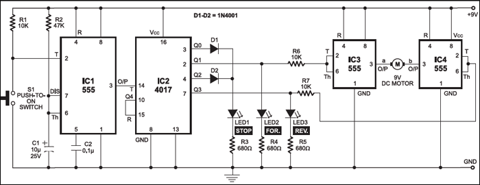
Suppose, initially, the circuit is in reset condition with Q0 output of IC2 being high. Since Q1 and Q3 outputs of IC2 are low, the outputs of IC3 and IC4 are high and the motor doesn’t rotate. LED1 glows to indicate that the motor is in stop condition.

Circuit operation
When you momentarily press switch S1, timer 555 (IC1) provides a pulse to decade counter CD4017 (IC2), which advances its output by one and its high state shifts from Q0 to Q1. When Q1 goes high, the output of IC3 at pin 3 goes low, so the motor starts running in clockwise (forward) direction. LED2 glows to indicate that the motor is running in forward direction.
Now if you press S1 again, the high output of IC2 shifts from Q1 to Q2. The low Q1 output of IC2 makes pin 3 of IC3 high and the motor doesn’t rotate. LED1 glows (via diode D2) to indicate that the motor is in stop condition.

Pressing switch S1 once again shifts the high output of IC2 from Q2 to Q3. The high Q3 output of IC2 makes pin 3 of IC4 low and the motor starts running in anti-clockwise (reverse) direction. LED3 glows to indicate that the motor is running in reverse direction.
If you press S1 again, the high output of IC2 shifts from Q3 to Q4. Since Q4 is connected to reset pin 15, it resets decade counter CD4017 and its Q0 output goes high, so the motor does not rotate. LED1 glows via diode D1 to indicate that the motor is in stop condition. Thereafter, the cycle repeats.
Construction & testing
If you don’t want to operate the motor in reverse direction, remove timer IC4 along with resistors R5 and R7 and LED3. And connect ‘b’ terminal of the motor to +Vcc.
Similarly, if you don’t want to run the motor in forward direction, remove timer IC3 along with resistors R4 and R6 and LED2. And connect ‘a’ terminal of the motor to +Vcc.
The circuit works off a 9V regulated power supply for a 9V DC motor. Use a 6V regulated power supply for a 6V DC motor.
For more circuit articles: click here
The article was first published in September 2004 and has recently been updated.


Can i get the report on this topic