


 You can make an ultra-simple desktop emergency light using ‘discharged’ batteries. You know that battery cells still have considerable energy left in them even when these become ‘weak’ for most battery-powered devices. Here is a way to extract their leftover power for use in such applications as emergency light.
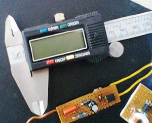
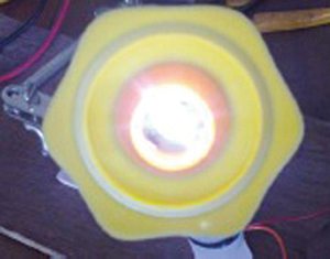
The LED light described here can be powered off any 1.5V or even a drained 1.2V battery cell. Fig. 1 shows author’s prototype and Fig. 2 shows the 1W white LED used.
Circuit and working
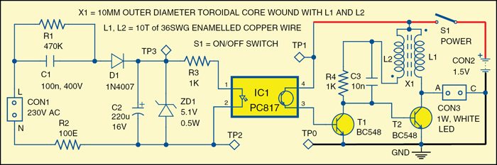
Fig. 3 shows the circuit diagram of desktop LED emergency light that comprises a combination of a joule thief circuit, a 1W white LED chip and a blackout detector section.

The front end of the circuit is a blackout detector for sensing the presence and absence of the grid power. Here, optocoupler PC817 (IC1) is connected to 230V AC mains supply through capacitor C1, diode D1, and resistors R1, R2 and R3. Voltage derived from AC mains is filtered by capacitor C2 and regulated by zener diode ZD1. This circuit section is used to control the switching of the joule thief circuit built around transistor T2, capacitor C3, resistor R4, and inductors L1 and L2. Resistor R4 limits the base current of transistor T2 and capacitor C3 improves the circuit efficacy.
 When switch S1 is closed and the battery is connected at CON2 (and AC mains supply is not available), current flows into the base of transistor T2, the voltage across its base and emitter rises and the transistor is switched on. This means that a larger current can now flow through primary winding L1 of transformer X1 and then through the transistor. This collector current generates a magnetic field in the toroidal transformer in a direction opposite to the field created by the base current through its secondary winding L2.
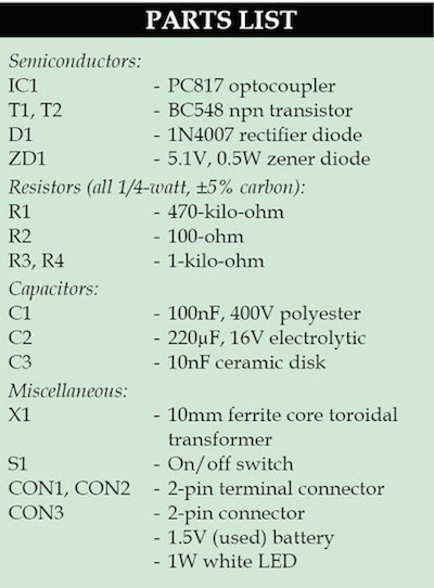
![]() As soon as the primary current becomes greater than the secondary current, the voltage on the secondary winding reverses which, in turn, switches off transistor T2. The magnetic field collapses and white LED is switched on. This allows the 1W white LED to be lit from a single 1.5V/1.2V battery, which otherwise required a 3.2V DC source or more.
As soon as the primary current becomes greater than the secondary current, the voltage on the secondary winding reverses which, in turn, switches off transistor T2. The magnetic field collapses and white LED is switched on. This allows the 1W white LED to be lit from a single 1.5V/1.2V battery, which otherwise required a 3.2V DC source or more.

![]() Download PCB and component layout PDFs: click here
Download PCB and component layout PDFs: click here
Construction and testing
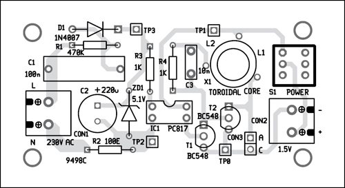
An actual-size, single-side PCB for the emergency light is shown in Fig. 4 and its component layout in Fig. 5. After assembling the circuit on PCB, enclose it in a suitable plastic box. When 230V AC mains supply is available, white LED is off—irrespective of the position of switch S1. When AC mains supply is off, switch S1 should be closed to make white LED glow and opened to switch it off.
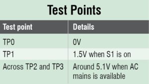
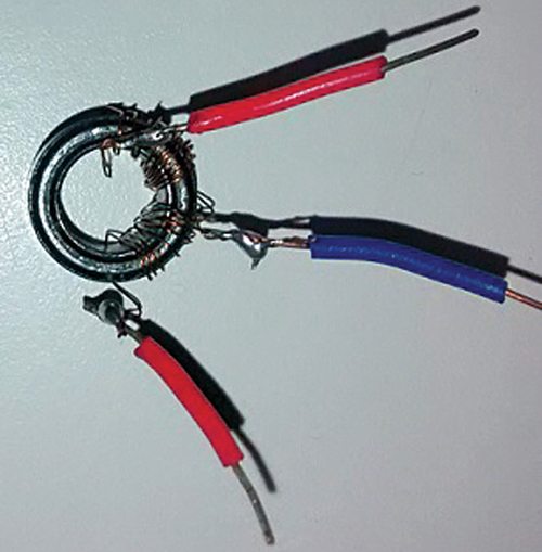
For the winding on toroidal core, take a small toroidal core (for example, one with 10mm outer dia and 5mm height). Wrap a 36SWG enamelled copper wire around the toroidal core to make 10 turns. Repeat the winding with the second piece of 36SWG enamelled copper wire. The two windings (L1 and L2) should be in opposite directions. The polarities of the windings are shown by the dots in the circuit. Now join nearest ends of the coils together, as shown in Fig. 6. This forms the centre pole which is connected to positive terminal of the battery. Before using the circuit, verify the voltages are as per table.
Caution: The circuit operates off live 230V AC mains, so take all the necessary safety precautions while building and using this circuit to avoid any nasty electric shock.
The author is a freelance writer and circuits designer.
