Here’s a digital stop watch built around timer IC LM555 and 4-digit counter IC with multiplexed 7-segment output drivers (MM74C926).
IC MM74C926 consists of a 4-digit counter, an internal output latch, npn output sourcing drivers for common-cathode, 7-segment display and an internal multiplexing circuitry with four multiplexing outputs. The multiplexing circuit has its own free running oscillator, and requires no external clock. The counter advances on negative edge of the clock. The clock is generated by timer IC LM555 (IC1) and applied to pin 12 of IC2.A high signal on reset pin 13 of IC2 resets the counter to zero. Reset pin 13 is connected to +5V through reset push-on-switch S3. When S2 is momentarily pressed, the count value becomes 0, transistor T1 conducts and it resets IC1. Counting starts when S2 is in ‘off’ condition.
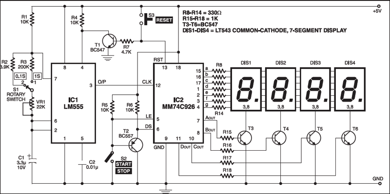

A low signal on the latch-enable input pin 5 (LE) of IC2 latches the number in the counter into the internal output latches. When switch S2 is pressed, pin 5 goes low and hence the count value gets stored in the latch. Display-select pin 6 (DS) decides whether the number on the counter or the number stored in the latch is to be displayed. If pin 6 is low the number in the output latch is displayed, and if pin 6 is high the number in the counter is displayed. When switch S2 is pressed, the base of pnp transistor T2 is connected to ground and it starts conducting. The emitter of T2 is connected to DS pin of IC2. Thus, when switch S3 is pressed, reset pin 13 of IC2 is connected to ground via transistor T1 and the oscillator does not generate clock pulses. This is done to achieve synchronisation between IC1 and IC2.
First, reset the circuit so that the display shows ‘0000.’ Now open switch S2 for the stop watch to start counting the time. If you want to stop the clock, close switch S2.

Rotary switch S1 is used to select the different time periods at the output of the astable multivibrator (IC1). The circuit works off a 5V power supply. It can be easily assembled on a general-purpose PCB. Enclose the circuit in a metal box with provisions for four 7-segment displays, rotary switch S1, start/stop switch S2 and reset switch S3 in the front panel of the box.