


This motor starter protects single phase motors against voltage fluctuations and overloading. Its salient feature is a soft on/off electronic switch for easy operation.
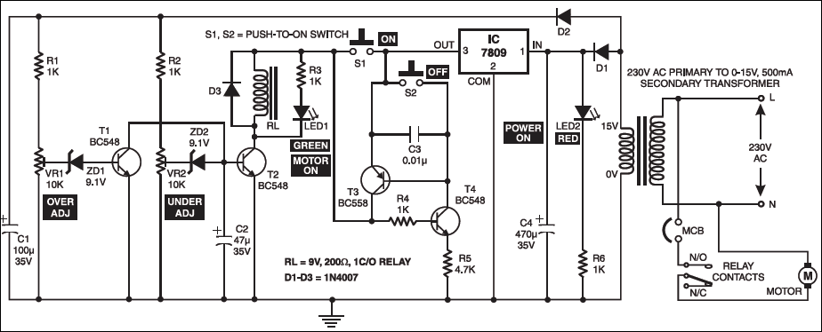
The transformer steps down the AC voltage from 230V to 15V. Diodes D1 andD2 rectify the AC voltage to DC. The unregulated power supply is given to the protection circuit.
In the protection circuit, transistor T1 is used to protect the motor from over-voltage. The over-voltage setting is done using preset VR1 such that T1 conducts when voltages goes beyond upper limit (say, 260V). When T1 conducts, it switches off T2. Transistor T2 works as the under-voltage protector. The under-voltage setting is done with the help of preset VR2 such that T2 stops conducting when voltage is below lower limit (say, 180V). Zener diodes ZD1 and ZD2 provide base bias to transistors T1 and T2, respectively. Transistors T3 and T4 are connected back to back to form an SCR configuration, which behaves as an ‘on’/‘off’ control. Switch S1 is used to turn on the pump, while switch S2 is used to turn off the pump.

While making over-/under-voltage setting, disconnect C2 temporarily. Capacitor C2 prevents relay chattering due to rapid voltage fluctuations.
Regulator IC 7809 gives the 9V regulated supply to soft switch as well as the relay after filtering by capacitor C4. A suitand D2 rectify the AC voltage to DC. The unregulated power supply is given to the protection circuit.

In the protection circuit, transistor T1 is used to protect the motor from over-voltage. The over-voltage setting is done using preset VR1 such that T1 conducts when voltages goes beyond upper limit (say, 260V). When T1 conducts, it switches off T2. Transistor T2 works as the under-voltage protector. The under-voltage setting is done with the help of preset VR2 such that T2 stops conducting when voltage is below lower limit (say, 180V). Zener diodes ZD1 and ZD2 provide base bias to transistors T1 and T2, respectively. Transistors T3 and T4 are connected back to back to form an SCR configuration, which behaves as an ‘on’/‘off’ control. Switch S1 is used to turn on the pump, while switch S2 is used to turn off the pump.
While making over-/under-voltage setting, disconnect C2 temporarily. Capacitor C2 prevents relay chattering due to rapid voltage fluctuations.
Regulator IC 7809 gives the 9V regulated supply to soft switch as well as the relay after filtering by capacitor C4. A suitable miniature circuit breaker is used for automatic over-current protection. Green LED (LED1) indicates that the motor is ‘on’ and red LED (LED2) indicates that the power is ‘on’. The motor is connected to the normally-open contact of the relay.When the relay energises, the motor turns on.

Can I get a kit for this circuit
I want to detail circuit to start manfrture please guide us rakesh doshi 9377694666