


Electromechanical energy meters have been the standard for metering electricity since billing began. But these are now being gradually replaced by electronic digital energy meters.
Presented here is a simple energy meter using Analog Device’s ADE7757 chip for single-phase, 2-wire (phase and neutral) systems used in households. IC ADE7757 is a low-cost, single-phase solution for electrical energy measurement.
You can use this solution even for individual appliances to see how much energy they are consuming.
Its salient features are:
1. Can read up to 999999 units (kWh) with a resolution of 0.01 units
2. Designed for normal 230V AC and maximum line current of 30 amps
3. The meter count is 100 pulses/kWh, i.e., 100 pulses will be required to register one unit
Energy Meter Circuit

Fig. 2 shows the circuit diagram of the energy meter which is built around an energy-metering IC with integrated oscillator ADE7757 (IC1), microcontroller AT89c52 (IC2), EEPROM AT24C02 (IC3), 5V voltage regulator 7805 (IC5), opto-coupler MCT2E (IC4) and an LCD display.
IC ADE7757
It is a low-cost, single-chip solution for electrical energy measurement. In operation, the chip interfaces with a shunt resistor (used as the current sensor) and AC analogue voltage sensing the inputs and outputting the consumed power as explained below.
It has two analogue input channels designated as V1 and V2, respectively. Channel V1 (also called ‘current channel’) is used for current sensing and channel V2 (also called ‘voltage channel’) is used for voltage sensing.
The differential output from the current-sensing resistor is connected between V1P and V1N inputs, whilst the differential output signal proportional to the AC line voltage, obtained through a resistor divider, is connected between pins V2P and V2N.
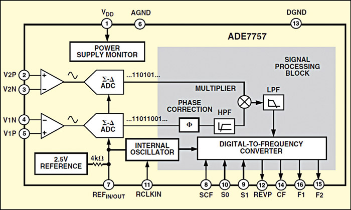
IC ADE7757 has a reference circuit and a fixed DSP function for the calculation of the real power. A highly stable oscillator integrated into the chip provides the necessary clock for the chip. It supplies the average real-power information on the F1 and F2 low-frequency outputs.
The meter is designed for 100 pulses/kWh and the pulses can be counted by any counter for power consumption calculation. Here, microcontroller AT89C52 is used for counting the pulses.
ADE7757 provides a high-frequency output at the calibration frequency (CF) pin (here, it is 3200 pulses/kWh), which is selected via S1 and S0 pins as shown in bold in Table II. This high-frequency output provides instantaneous real-power information, which is used to speed up the calibration process. The functional block diagram of ADE7757 is shown in Fig. 3.
The power supply for IC ADE7757 is derived directly from mains using the capacitor divider network comprising C13 and C14. Most of the voltage is dropped across C13 (0.47µF polyester capacitor rated for 630V), whilst resistor R11 (470-ohm, 1W) is used as the current limiter.
The output across C14 is limited to 15V DC, which serves as an input to regulator IC5. The regulated 5V is fed to IC1. The F1 output of IC1 is coupled to port pin P3.2 of microcontroller IC2 via opto-coupler IC4 whilst LED1 indicates that IC1 is working.
AT89C52
It is a low-power, high-performance CMOS 8-bit microcontroller that provides standard features: 8k bytes of Flash, 256 bytes of RAM, 32 I/O lines, three 16-bit timers/counters, a six-vector two-level interrupt architecture, a full-duplex serial port, on-chip oscillator and clock circuitry.
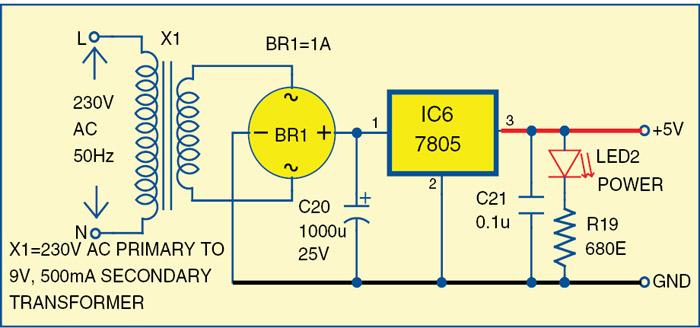
Microcontroller IC2 takes the energy meter reading through its pin 12 and stores it in EEPROM IC3, and at the same time displays it on the LCD, which requires an additional 5V regulated and isolated supply (to avoid extension of live mains to the counter section).
A conventional 5V regulator circuit incorporating a bridge rectifier (BR1), smoothing capacitor (C20) and regulator IC 7805 (IC6) has been used for the purpose. Fig. 3 shows the additional power supply.
Pins 21 through 28 of microcontroller IC2 are connected to the LCD data pins D0 through D7, respectively. pins 15, 16 and 17 of IC2 are connected with the control pins RS, R/W and EN of LCD, respectively.
The combination of resistor R14 and capacitor C16 provides a power-on reset. Switch S1 is used for manual reset. A 12MHz crystal along with two 22pF capacitors provides basic clock frequency to the microcontroller. Preset VR2 is connected with pin 3 of the LCD for contrast control.
Download the PDC and Component Layout PDF: Click Here
AT24C02
It is an I2C-bus compatible 2-kilobit EEPROM organised as 256×8 bits that can retain data for more than ten years. To obviate the loss of the latest setting in the case of power failure, the microcontroller can store all data of the user in the EEPROM.
The memory ensures that the microcontroller will read the last saved data from EEPROM when power resumes. Using SCL and SDA lines of EEPROM, the microcontroller can read/write the data from/to AT24C02 memory. SCL and SDA lines of IC3 are interfaced to pins 10 and 11 of microcontroller IC2, respectively.
Software
The source program for the microcontroller is written in C language and compiled using the ‘Keil µVision4’ compiler. The generated hex code is burnt into the microcontroller by using a suitable programmer. On reset/power-on, the microcontroller executes the main function. The interrupt INT0 and LCD are initialized first.
Message ‘Energy Meter’ and reading are displayed in the first and second lines on the LCD module. A continuous loop in the code reads the data from EEPROM and displays it in the second line of the LCD module. Header file i2c.h is used for I2C protocol communication and lcd.h is a driver file for LCD.
Download Source Code: Click Here
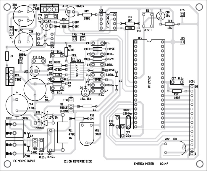
Construction and testing
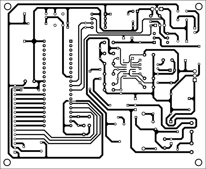
A single-side PCB for the energy meter is shown in Fig. 5 and its component layout in Fig. 6. Assemble the circuit on the PCB to minimize assembly errors. IC1 is an SMD package so should be soldered on the solder side of the PCB. Use IC bases for other ICs.
The author has a B.Tech in electronics and communications from Dr. AIT, Bengaluru

Hi
What is the value of the L1,L2 ,L3,L4?
Thanks Marius
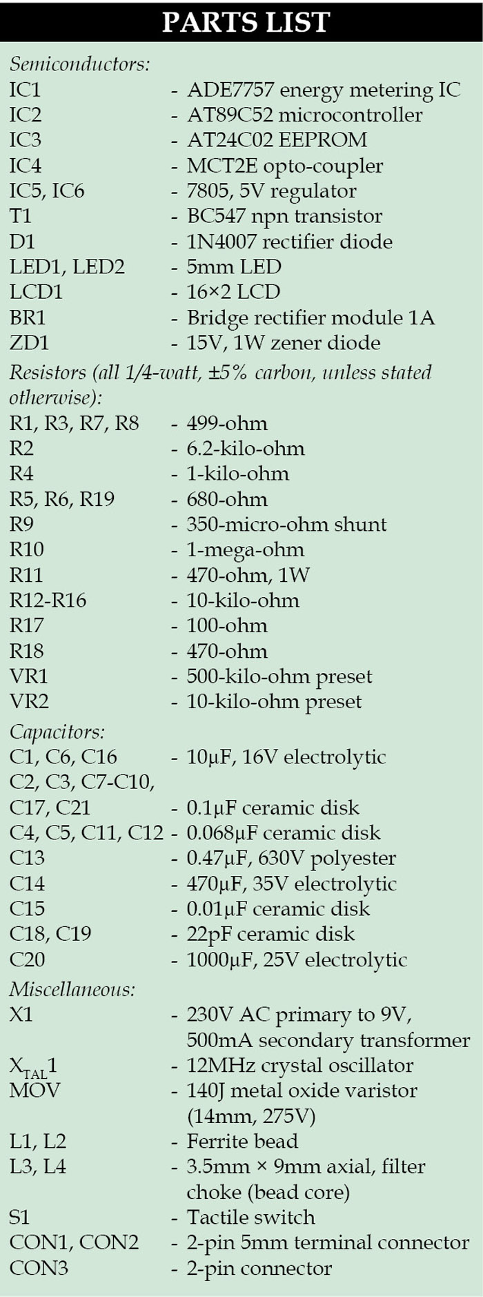
The details of L1 to L4 are given in the parts list. Ferrite beads with impedance up to 120 Ω and current of 200 mA may be used.
In which issue of EFY magazine cover this article ?
Dear JAYAPRASAD,
This article was covered in February 2014 EFY issue.
for coding which software is used
Hi
Can i interface GSM module with the same circuit. If so can i get some references for that.
I am thankful to you that the projects posted here are informative.
But the ICs used in this site are many times very Costly in India.
For example IC 74c926 used in Intruption counter project and the ic used in this projects(ADE7757 ) also…
Good Job! Please, I need help getting ADE7757 IC in Proteus. I can’t find the ADE7757 IC in Proteus. Please, is there alternative?
do you find it ?? I can’t find it too
Hi, did you guys end up finding the chip on Proteus? Or did you end up simulating the project on another simulation software?
Hello. Did you end up finding the ADE7757 IC in Proteus? Or did you use another simulation software?
Hello . I am student and my license project is this project i have some problems .i do download files but cannot run it on pdf and i want to add a gsm module. Please help me. And send files to my email address.Thanks you .
hello , I am student too and my license project is this same project i have some problems can you help me please .
Hi I am Akindele and I saw your project which interest me a lot at doing it myself and at least for my use at home please can you help me send the details about the the analog device used inclusive the source code. I am grateful.
What is the software is used to simulate?
Please help…How do i open the source code? Its a .rar file and I can not open it with Keil µVision.
Sir mnee aa pcb design karavavi 6 plz koi help kari sake 6 nd banavi apva ready hoy to ketla ruppes thase aee k jo plz
CAN i MEASURE kva kvah AND pf WITH THIS METER?
Can I interface GSM Module with the same circuit.
what is the proccess if i want to make 3 phase energy meter,can you help me with circuit diagram and coding.
Hello dear, Can i use PIC16F877A microcontroller instead of at89c52. Please Tell me.
Thank you
If you want to use PIC16F877A, you will have to redesign the whole circuit and program