


Just trigger an infrared electronic gun and there goes one invisible bullet hitting the bull’s eye, if timed properly. This shooting game circuit is very simple, inexpensive and easy to construct. The game offers hours of fun and excitement.
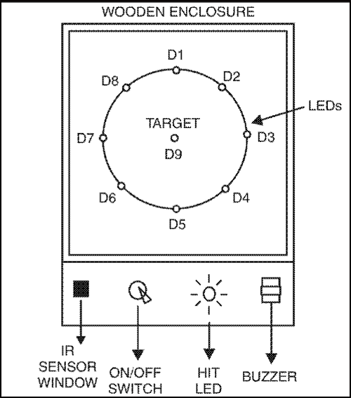
The target screen consists of a number of LEDs moving rapidly in a circular fashion. All the LEDs are red except one—the real target located in centre of the screen which is green. When a shot is fired by triggering the gun, all LEDs go off except one. If it happens to be the target (green LED) then you have made a hit which is indicated by lighting up of another green LED accompanied by a pleasing musical tone. After a short delay the game restarts automatically.
Electronic Shooting Game
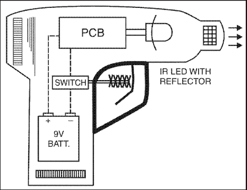
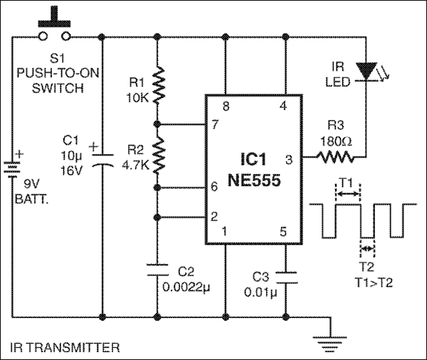
Infrared gun (transmitter) for this electronic game is built around IC1 timer (NE555) wired as an astable multivibrator with a centre frequency of about 35 kHz. The frequency is determined by the timing components comprising resistors R1 and R2 and capacitor C2. When push-to-on trigger switch S1 is pressed, the astable multivibrator starts modulating the infrared beam with short pulses (See output waveform). The whole circuit can be enclosed in a toy gun for giving it a professional look as illustrated in the figure. The infrared LED has to be fitted with a suitable reflector to ensure good sensitivity.
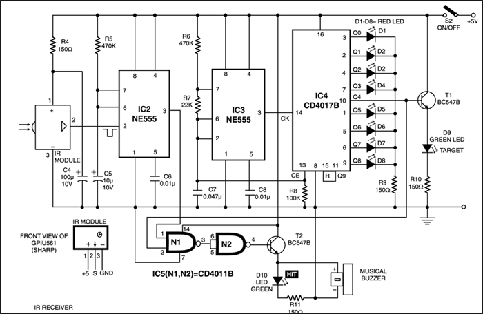
When power switch S2 in the receiver is turned on, astable multivibrator wired around IC3 (NE555) generates clock pulses which are fed to clock input (pin 14) of decade counter IC4 (CD4017B). This IC has ten outputs, and each one goes high sequentially on the rising edge of successive clock pulse. As a result, LEDs connected to the output appear to move from one to the other rapidly. You would notice that only nine outputs are used for driving LEDs. The tenth output (Q9) at pin 11 is connected to reset pin 15.
Circuit operation
When gun is fired, infrared bursts are received by the integrated infrared module and its output at pin 2 goes low. The resulting falling edge triggers monostable IC2 and its output (pin 3) goes high. This makes clock enable (CE) pin 13 of IC4 to go high (normally held at a low potential via resistor R8) and it starts counting. When mono pulse ends, and if the last lit LED happens to be the target LED then both inputs of NAND gate N1 become high. As a result, the output of gate N2 also goes high. This in turn switches on transistor T2; thereby the ‘HIT’ LED lights up and the buzzer also sounds. At the end of the mono pulse period (about 5 secs), decided by resistor R5 and capacitor C5, the mono IC2 is again ready to receive another trigger pulse.
Assembly and component layout is not very critical. The circuit may be assembled on a veroboard using IC sockets. A well regulated power supply is required for powering the unit. In place of the IR transmitter it is also possible to make use of the remote control used for TVS or VCPs/ VCRs.
The article was first published in November 2006 and has recently been updated.
More info about the project would be great
And i am not able to understand how will u target the green led and where will we place the ir module in the project