


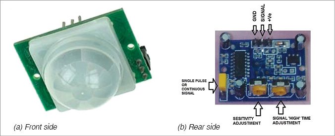
 Quite often you forget to switch off the light or fan when going out of the room. The simple infrared sensor based power saver circuit presented here will automatically switch off electrical appliances like lights or fans as you vacate a room, after a predetermined time period. It will also switch on the light when you enter the room again. This will reduce unnecessary power consumption. Fig. 1 shows the pyroelectric/passive infrared (PIR) motion sensor used in the circuit.
Infrared sensor based power saver circuit
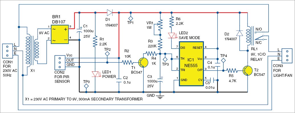
 The circuit diagram of the infrared sensor based power saver is shown in Fig. 2. It is built around bridge rectifier DB107 (BR1), PIR motion sensor connected across connector CON2, timer NE555 (IC1), two 1N4007 rectifier diodes (D1 and D2) and a few other components.
The circuit uses a PIR sensor, which detects the presence of people through change in the infrared radiation from the room when people enter or leave the room. The PIR sensor outputs around 3.3V high signal whenever it detects radiation change in front of it.
IC1, resistor R3, potmeter VR1 and capacitor C3 are used as a timer here to convert small time span of PIR signal to a long delay. Output of IC1 at pin 3 drives transistor T2, which, in turn, controls relay RL1. Electrical loads like lights or fans are controlled through this relay.
 230V AC mains power is connected across connector CON1. It is stepped down to 9V through transformer X1, rectified by bridge rectifier BR1 and filtered by capacitor C1. Thus we get around 9V DC at test point TP1. This 9V DC voltage is used as power supply for the circuit.
Circuit operation
When the circuit is first switched on, capacitor C3 charges through potmeter VR1 and resistor R3. During this time, voltage at pins 2 and 6 of IC1 is less than two-thirds of its supply voltage, and so output pin 3 goes high. This energises the relay through transistor T2, and the appliance is switched on.
When capacitor C3 charges above two-thirds of the supply voltage, IC1’s output pin 3 goes low and de-energises the relay and switches off the appliance after some delay that can be adjusted through potmeter VR1.
Whenever motion is detected by the PIR, its output pin goes high (around 3.3V) for a while depending on the setting on the PIR. The high signal from the PIR is fed to the base of transistor T1, which, in turn, discharges capacitor C3 through resistor R4. When the capacitor’s charge (voltage) reaches less than two-thirds of the power supply, output pin 3 of IC1 goes high again (initial stage) and load is switched on.
When the load is switched off, LED2 glows. This indicates that the circuit is under power-save mode.
Construction and testing
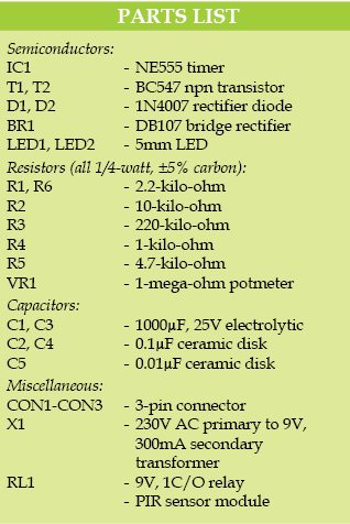
A single-side PCB for the PIR sensor based power saver is shown in Fig. 3 and its component layout in Fig. 4. Enclose the PCB in a small box in such a way that you can easily connect 230V AC input to CON1 and the light/fan to CON3 at rear end of the box. Connect the PIR using a 3-wire cable to the PCB at CON2 and install it at a suitable location in your room.
Before using the PIR in the circuit, manually check it by connecting Vcc and GND pins of PIR to a 9V (or 12V) battery. Then check for change in voltage at signal output pin with respect to ground by waving your hand in front of the sensor. Adjust sensitivity and time controls of the PIR as per requirement (else turn both presets clock-wise to have highest sensitivity and high time signal). The dome surface of the PIR should be clean for better sensing.


Download PCB and component layout PDFs: click here
After manually checking the PIR, remove the battery and connect the PIR to the PCB. You can assemble the circuit on the PCB with terminal connectors for CON1 (input) and CON3 (output).
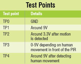
Verify that voltages at the test points are as per the table before using the circuit. Check to see if LED2 is off and relay is energised. After some time, LED2 will glow and the relay will get de-energised. Your circuit is now ready!
EFY notes
Some PIR sensors require an initial stabilisation time of 10 to 60 seconds in order to function properly. During this time, any motion in its field-of-view (near 15m range) should be avoided.
Main DC voltage at TPI is unregulated.
Feel interested? Check out other electronics projects.
Hello sir….
I am Divyanshu
Sir i am trying to make a circuit of Infrared Sensor Based Power Saver.I connected all the components as per your circuit diagram but my circuit is not work. Then I check the voltage of TP1 . only 3.5 volts at TP1
Sir you tell what is wrong in my circuit plzzz
Your problem is not clear whether the components are heated up excessively while measuring the voltage at TP1. If yes, there is a possible short circuit.
First make sure that transformer output is about 9V. Remove IC1 and T1 from circuit and check the voltage at TP1 again, it should be around 9V as listed in the test point table. Also check voltage between pin 3 and 4 of BR1 which should be about 9V.
If not, double check BR1 connections or replace it with a fresh one. The circuit is simple and working perfectly. It will work if all components are connected properly in the circuit as shown in Fig.2.
Transformers output is 9V but BR1 output is 8.2V
Sir here I used KBP210 bridge rectifier because DB107 is not available in my area
sir my bulb starts but it is not off automatically please sir quick reply
To switch off the relay, no person should stand or move infront of the PIR and wait for long time.
to change the delay of relay OFF time, adjust the 1M variable resistance.
Change capacitor c3 if it’s high value the bulb on duration is high that’s the reason I think…
Can i get this project kit
@ Shiva Samrat : Kit isn’t available for this project. But you may visit kitsNspares.com where you can get wide range of DIY projects with all required components and PCB.
Can we use 9v supply to sensor input that you have given in circuit or we have to use a IC7805 extra to circuit you have guven to decrease voltage for sensor
Yes you can. Its power supply range is 5V – 20V. No extra circuit required.
Can i know the potmeter is connected as adjusted or fixed 1M value?
You have to use multimeter to measure the value of VR1.
I made this project.It is in running condition but i found one major fault in this circuit. 220k ohm resistor causes too much voltage drop . I removed potentiometer of 1M ohm and 220k ohm resistor and and i placed 2.2k ohm in it.
@ Muhammad farhan. This is the reply from author Fayaz Hassan. I felt happy to know that somebody tried the circuit and it is working fine.
The main purpose of the 1M and 220K resistance is to slowly charge the capacitor C3 (1000uF), so that it increases time delay of the PIR which has limited triggering time. In case, the capacitor has more internal leakage than the charge input through the 1M and 220K, then the capacitor C3 will never get charged and the output of IC1 (555) will never change. so use new and good quality capacitor with atleast 25V rating. By changing the charging resistance, only relay hold time will vary else the circuit will function normally.
Sir ,
Can this project automatically switch ON or OFF light and fan .
Can This project automatically work if two man or three man enter but one man out in the room??
Pls reply this question .
If it is not work then how solve this problem.
Its my CLG project.
This is the reply from the author. Yes, it works. It does not count the persons. Actually, the PIR sensor triggers whenever a person is moved in front of it. (of course, within its range. refer datasheet for full details) if the person is not moved for more time, the relay will be switched OFF.
It means the relay may be switched OFF if the person is sleeping (if no movement is observed for a long time). So the time delay is adjusted with 1M variable resistance. Use good quality and fresh capacitor C3 (1000uF) to have low leakage and high delay time. Also please read 2nd paragraph of Construction and Testing section.
Sir,
please give me a block diagram of infrared sensor based power saver without using microcontroller. In the circuit diagram we are not use the microcontroller so please give me some idea about block diagram.
can u please put a video of it……
hello sir , i want to add LDR in this circuit but where please help.
Sir can you tell me that what’s the cost of this project?
We are implementing it on a lot of rooms.
You can assemble it in less than Rs 1000
I have prepared this project for our office corridor. while i was trying to check the voltage at Test point 1 (TP-1), multimeter was showing descending volt up to 0 volts instead of 9 volts. the transformer which I have used was showing 10 volts. and the DB107 rectifier showing 13 volts at its terminal. te voltage after filter capacitor is -6.5 volt. for any short circuit probability, i have brake the further circuit but it still showing the same result. please help me.
Can I get the kit of pir motion sensor
Can I use 12v relay instead of 9v relay&
What type of three pin connector we have to use
No, you have to use 9V relay. You can use 3-pin Berg strip connector
What mode of operation is 555 working on
for atleast how long will the electric appliance operate? how can we increase the time it operates? by decreasing the 1 mega ohm value of variable resistance?
i dont have 9 v transformer and 9 v relay available in my area. Can i use 12 v transformer and 12 v relay?