


This intelligent switch circuit enables automatic, switching on of an emergency light system during darkness in the event of mains failure. The mains power failure condition is detected by the section consisting of mains step-down transformer X1 followed by bridge rectifier comprising diodes D1 through D4 and smoothing capacitor C1. If the mains is available then it causes energisation of relay RL1 which has two sets of changeover contacts.
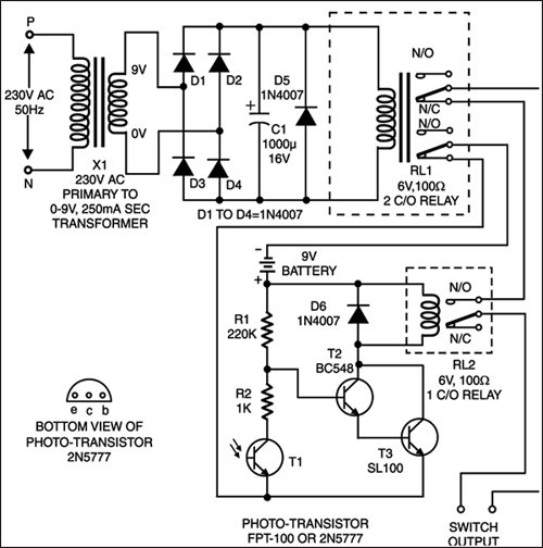
The light/darkness condition is detected by the circuit comprising photo transistor FPT100/2N5777 followed by Darlington pair comprising transistors T2 and T3. However, this section will function only when mains supply is not available (i.e. when relay RL1 is in de-energised state) since battery supply (negative lead) path gets completed via lower N/C contact of relay RL1.

During daylight, photo transistor conducts and places transistor T2 base near ground potential. Thus Darlington pair remains cut-off and relay RL2 remains de-energised. However, during darkness, photo transistor is cut-off and therefore transistor T2 receives forward base bias via resistor R1 (connected to positive rail), as resistor R2 is no more grounded (via photo-transistor T1). As a result, relay RL2 gets energised.
Thus it would be observed that when mains is absent (relay RL1 de-energised) and it is dark (relay RL2 energised), the switch output path is complete. In any other condition switch output path would get broken. The switch output terminals can be used (in series with supply) to control a lighting system directly or indirectly through another contactor heavy-duty relay depending upon the load.

The working of the intelligent switch is summarised in the table.


sir isme load kitna de skte hai
mtlb 100 watt k bulb chla skte hai
thanku