


 Here is a circuit that starts counting when you insert a letter in the letterbox at your home or office. It is designed to save your time from going to the letterbox to check if there are letters inside. The number of letters present in the box is indicated by a seven-segment display. The block diagram of the circuit is shown in Fig. 1.
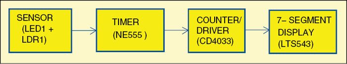
Circuit and working
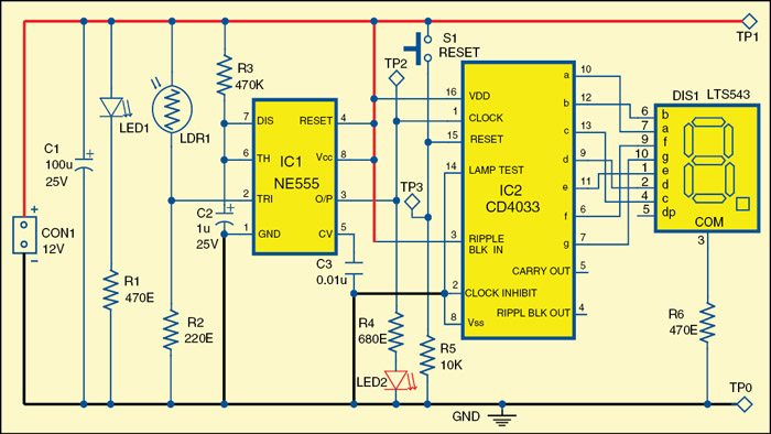
Fig. 2 shows the circuit diagram of the electronic letterbox with letter-counting facility. It is built around a white LED (LED1) and an LDR (LDR1), popular timer NE555 (IC1) in monostable mode, a counter, seven-segment driver CD4033 (IC2) and a few other components. LED1 and LDR1 together work as a sensor.

The resistance of LDR1 changes in accordance with the intensity of light incident on it. When light from LED1 falls on LDR1, its resistance is low.
Voltage at pin 2 of IC1 depends on the light falling on LDR1. In the dark, voltage at pin 2 is low, and vice-versa.
When a letter is inserted into the letterbox, it passes between LED1 and LDR1. This interrupts the light falling from LED1 to LDR1. As a result, resistance of LDR1 increases. This change in resistance provides a triggering pulse to pin 2 of IC1, generating a short-duration square-wave pulse at its output pin 3. This pulse acts as clock input for the counter and display driver CD4033 (IC2). Output pins of IC2 are connected to various segments a, b, c, d, e, f and g pins of seven-segment display (DIS1) as shown in the circuit. Its common pin 3 is connected to ground through current-limiting resistor R6. Alternatively, you can also provide a resistor each for each segment after removing resistor R6. Seven-segment display DIS1 displays the number of letters present in the box up to nine.
When a letter is delivered to the letterbox, LED2 momentarily glows, which indicates that a letter is received and DIS1 increments the display by one count. That is, for each pulse received at input pin 1 of IC2, its output advances by one count, which is reflected in the seven-segment display. When the counter reaches nine, it automatically resets to zero and the cycle repeats. Switch S1 is used to reset the counting.
After collecting the letter from the letterbox, always reset the counter using switch S1.
Download PCB and Component Layout PDFs: Click here
Construction and testing
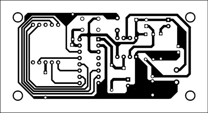
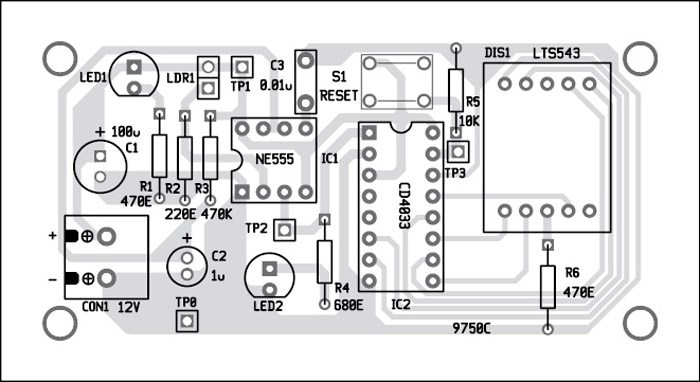
An actual-size, single-side PCB for the letterbox circuit is shown in Fig. 3 and its component layout in Fig. 4. Enclose the PCB in a suitable box in such a way that light from LED1 falls on LDR1. Ensure proper wiring to avoid any mistake. For troubleshooting, check the voltages at various test points as listed in the table.
Vandana Sawant is assistant professor (electronics and telecommunication), and Rachna Patil, Ratuja Patil, Kirti Pawar and Greeshma Pillai are third-year engineering students at SIES Graduate School of Technology, Navi Mumbai

my friend can i have list of components this project??
My you send the list of the components required for this project.