 If you need a lid monitor sensor system for an application, this is the circuit you have been looking for. One application for such sensors would be in the security market. For example, construction companies need more ways to combat tools theft. Construction toolboxes typically remain on a construction site when the workers leave, making these easy targets for theft. Lid-monitoring sensors can be used to detect when a toolbox is being opened or tampered with, among other things, which can be used in conjunction with a microcontroller (MCU) based monitoring device.
Here is a simple lid monitor sensor module circuit realised using an inexpensive mercury-free tilt switch. The standalone roller-ball-type tilt sensor senses tilt angle/movement, and its overall response is very fast.
Circuit and working for lid monitor Sensor Module
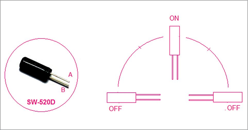
A look at Fig. 1 will convince you that the circuit diagram of the lid monitor sensor module is pleasantly simple. Admittedly, a roller-ball-type tilt sensor (SW-520D) is used here. Such a device consists of two conductive elements (poles) and a conductive free mass (rolling ball), encapsulated in the same case. When the tilt sensor is oriented so that that end is downwards, the mass rolls onto the poles and shorts these, acting as a switch throw. Working principle of SW-520D tilt sensor is shown in Fig. 2.
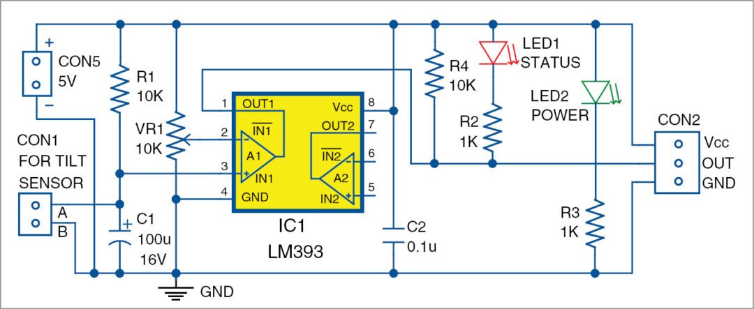
Rest of the circuit is based on a ‘misused’ LM393 (IC1) configured as a simple RC op-amp comparator timer. In idle state, voltage is applied across the R1-C1 combination, producing a typical RC charging signal that is fed to the non-inverting input (pin 3) of IC1.
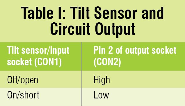
 As capacitor C1 charges to a value above IC1’s reference voltage, IC1’s output (pin 1) turns from low to high, disabling current flow through the pull-up resistor (R4) and through the LED (LED1). Time delay can be controlled by changing values of R1/C1 or by adjusting the value of trimmer resistor (VR1) connected to the inverting input (pin 2) of IC1. As a result, output of IC1, available through the middle pin (OUT) of the MCU-compatible output socket (CON2), is high (H) in idle state.
When the tilt sensor, linked to the input socket (CON1), is activated by a valid-tilt, C1 is discharged through the tilt switch and a new time cycle occurs. Now, output of IC1 changes to low (L) state, making LED1 to glow for a finite time, here around one second. Table I may be easier to understand than the schematics.
Construction and testing for lid monitor Sensor Module
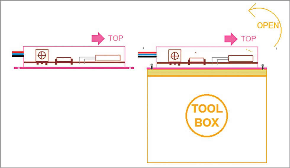
A small circuit board can hold nearly all components. After everything has been properly connected together, you can fit everything into an enclosure, shown in Fig. 3. The finished system can be installed on any surface. For greater accuracy, the system could be mounted using mechanical threading, magnets or adhesives, depending on the type of surface it is being mounted to. Note that a PCB design allows the system to be built in a very compact form, which can be an important factor if it has to be fitted into an existing piece of equipment. Fig. 4 shows the proposed mounting plan of the lid-monitor sensor module.
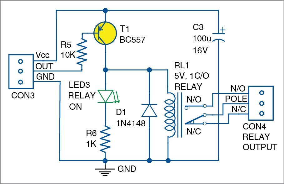
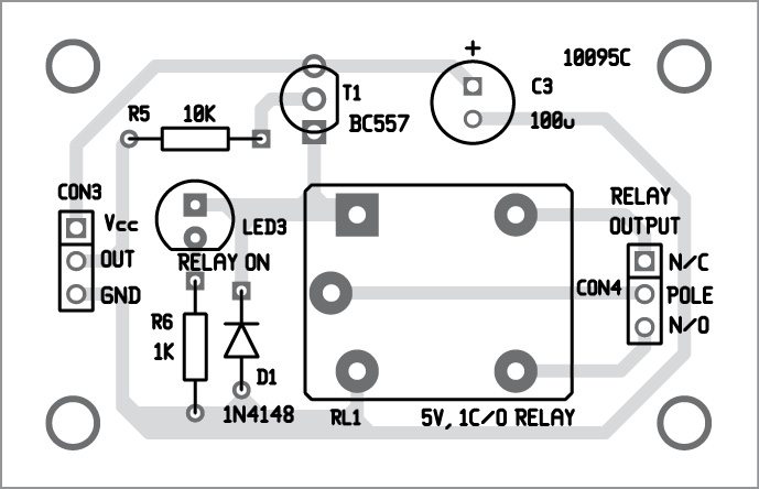
Although the circuit is designed for interfacing with an MCU unit, in many cases it will be necessary to provide an electromechanical switch at the output such that an external electrical load can be switched with great galvanic isolation. An electromagnetic relay can often be used for this purpose as shown in Fig. 5. Since relay contacts are used for switching, load can be of any type: high voltage, low voltage, resistive, capacitive or inductive.
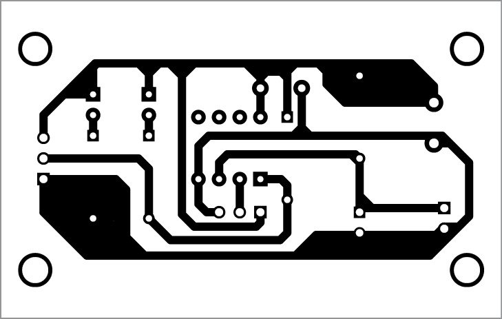
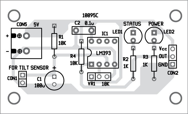
An actual-size, single-side PCB for the lid-monitor sensor module is shown in Fig. 6 and its component layout in Fig. 7. Similarly, an actual-size, single-side PCB for the electromechanical switch is shown in Fig. 8 and its component layout in Fig. 9. You can interface the MCU unit with this circuit through CON2.
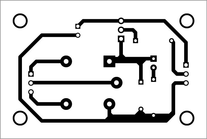
Download PCB and component layout PDFs: click here
If the MCU unit is not used, connect CON2 to CON3 of the electromechanical switching unit. This unit works off a 5V, regulated DC power supply. Enclose both PCBs of the sensor module and the switching unit in a box.
Design Idea+
This circuit is ideal for applications sensing closure of an assortment of different lids and/or caps. Next example could be to sense whether the gas-filling lid and the gas cap of an automobile are in place or not. Demand for such systems is increasing because gas-filling lids and gas caps can remain open due to carelessness of the vehicle operator or of a service attendant. Any potential arc or spark in and around the gas could ignite the fuel.
For more exciting DIY projects: click here
T.K. Hareendran is founder and promoter of TechNode Protolabz