


When ever AC mains supply fails, this mains supply failure alarm circuit alerts you by sounding an alarm. It also provides a backup light to help you find your way to the torch or the generator key in the dark.
Mains Supply Failure Alarm Circuit
The circuit is powered directly by a 9V PP3/6F22 compact battery. Pressing of switch S1 provides the 9V power supply to the circuit. A red LED (LED2), in conjunction with zener diode ZD1 (6V), is used to indicate the battery power level. Resistor R9 limits the operating current (and hence the brightness) of LED2.
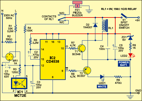
When the battery voltage is 9V, LED2 glows with full intensity. As the battery voltage goes below 8V, the intensity of LED2 decreases and it glows very dimly. LED2 goes off when the battery voltage goes below 7.5V.

Initially, in standby state, both the LEDs are off and the buzzer does not sound. The 230V AC mains is directly fed to mains-voltage detection optocoupler IC MCT2E (IC1) via resistors R1, R2 and R3, bridge rectifier BR1 and capacitor C1. Illumination of the LED inside optocoupler IC1 activates its internal phototransistor and clock input pin 12 of IC2 (connected to 9V via N/C contact of relay RL1) is pulled low. Note that only one monostable ofdual-monostable multivibrator IC CD4538 (IC2) is used here.
Circuit operation
When mains goes off, IC2 is triggered after a short duration determined by components C1, R4 and C3. Output pin 10 of IC2 goes high to forward bias relay driver transistor T1 via resistor R7. Relay RL1 energises to activate the piezobuzzer via its N/O contact for the time-out period of the monostable multivibrator (approximately 17 minutes). At the same time, the N/C contact removes the positive supply to resistor R4. The time-out period of the monostable multivibrator is determined by R5 and C2.
Simultaneously, output pin 9 of IC2 goes low and pnp transistor T2 gets forward biased to light up the white LED (LED1). Light provided by this back-up LED is sufficient to search the torch or generator key.
During the mono time-out period, the circuit can be switched off by opening switch S1. The ‘on’ period of the monostable multivibrator may be changed by changing the value of resistor R5 or capacitor C2.
If mains doesn’t resume when the ‘on’ period of the monostable lapses, the timer is re-triggered after a short delay determined by resistor R4 and C3.
The article was first published in May 2004 and has recently been updated.