


 Servo motors are widely used in precise control applications, but most of them can rotate up to 180 degrees only. Presented here is a process for modifying servo motors so that these can rotate up to 360 degrees in either direction (clockwise and anticlockwise). This would permit the motors’ use for wider applications without using additional controllers.
The modification of a servo motor can be done using the following components and tools:
1. Two 2.2k, ±1%, 0805 resistors
2. Soldering iron
3. Multimeter
4. Wirecutter
5. Precision screwdriver
De-assembling the servo motor
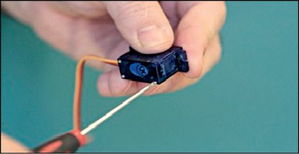
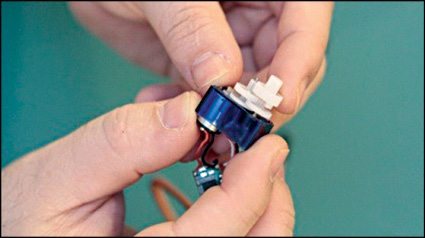
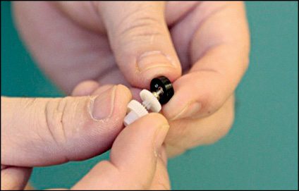
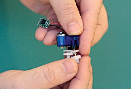
- Remove any tags or stickers from the body of motor and open its front cover by removing the screws holding the motor together, as shown in Fig. 1.
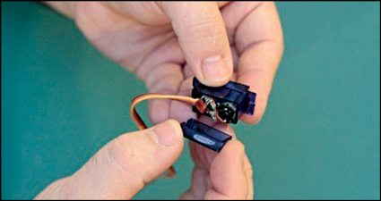
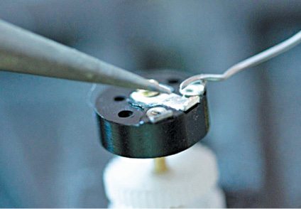
- Slowly open the front cover. There is circuit board, potentiometer and motor inside the casing, as shown in Fig. 2.
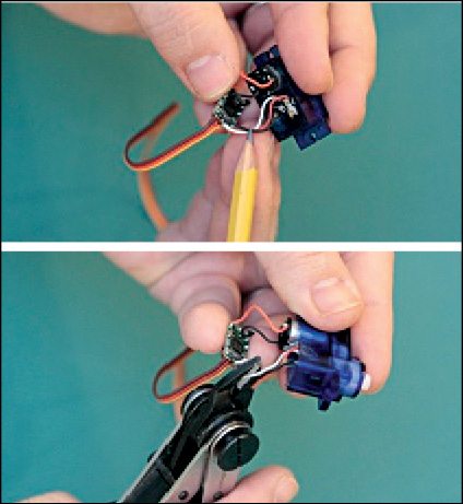
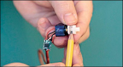
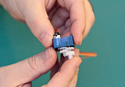
- There are two sets of wires; one coming out of the motor and one coming out of the potentiometer. Cut the wires coming out of the potentiometer and do not damage the wires coming out of the motor, as shown in Fig. 3.
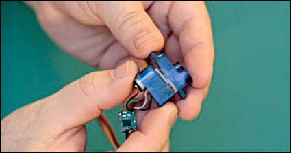
- Open the top cover of motor to take out the potentiometer, as shown in Fig. 4.
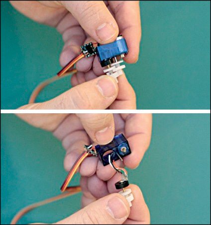
- Pay attention to the gear configuration (better take a photograph of it) as this will be needed during re-assembly, as shown in Fig. 5.
- The knob shown in Fig. 6 helps limit the servo’s movement.
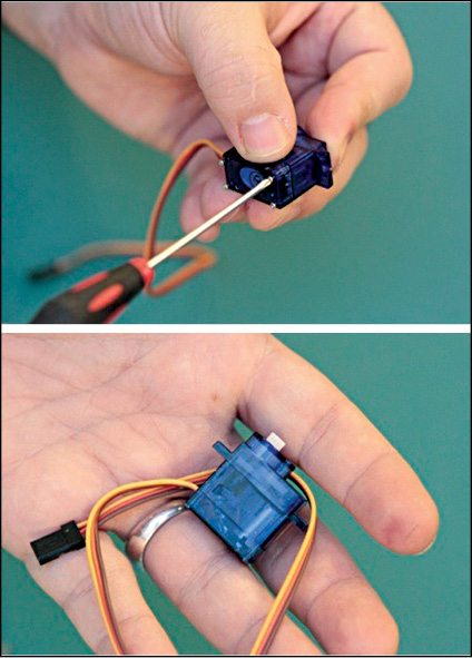
- Slowly pull the gear arrangement and potentiometer out of the casing. Try to minimise the movement between the gear arrangements. Cut the wires hanging from potentiometer, as shown in Fig. 7.
Breaking the motion-hindering points
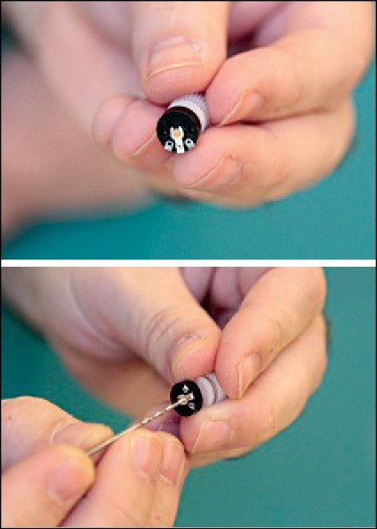
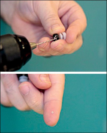
8. To break the motion-hindering points, the rim of the rivet needs to be removed. For doing so choose a drill bit that is a little bigger than the inner hole of the tiny rivet, as shown in Fig. 8.

9. While drilling, do not press hard and try not to get any grease on contact. Stop drilling as soon as doughnut-shaped rim of the rivet drills out, as shown in Fig. 9.
10. Now remove the end-stop and put it aside, as shown in Fig. 10.
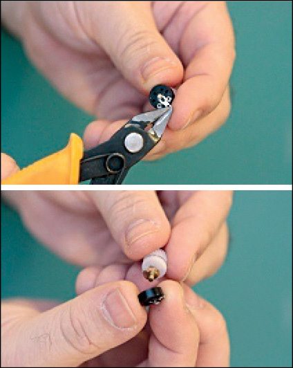
11. The bumps on the potentiometer also help in preventing a continuous rotation, but breaking these will damage the motor. So follow the technique mentioned below:
The limiter and foil contact are pressed close together. Remove the limiter using pliers or cutter, as shown in Fig. 11.
12. Detach the limiter completely without affecting the shaft. The foil contacts will come off easily. Remove the limiter by snipping it, as shown in Fig. 12.
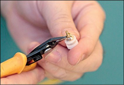
13. Now remove the knob (mentioned in step 6), as shown in Fig. 13.
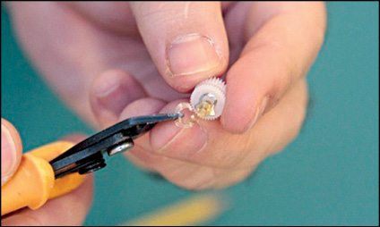
14. Put the shaft and its end-stop back to original position (apply some petroleum jelly on shaft inner side), as shown in Fig. 14.

Modification
15. For modification, solder the rivet back in its position, as shown in Fig. 15. Spin the shaft to ensure it rotates easily.
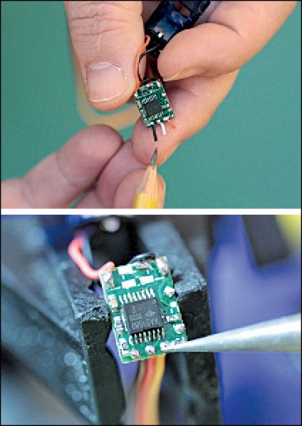
16. De-solder the wires from the driver board, as shown in Fig. 16.
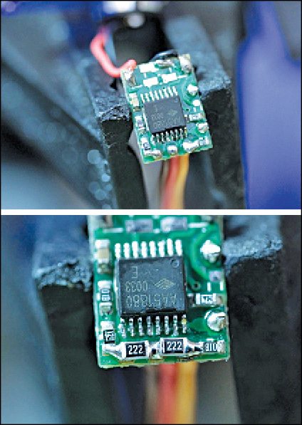
17. Mount two resistors to make the driver sense that the potentiometer is always on its centre position. The resistors should be of 1% tolerance to ensure the precision required. The value of the resistors should be 2.2-kilo-ohm each, and 0805 package, as shown in Fig. 17.
Re-assembly
18. Re-assemble all the parts of gear assembly in their correct order (refer to the previously-clicked pictures of the gear assembly), as shown in Fig. 18.
19. Push potentiometer back into the case, as shown in Fig. 19. Do not try to rotate the gear assembly at this time.
20. Put back the PCB inside the case. Ensure that all the wires properly fit inside the housing and none of them is getting pinched. Put the screws back and the servo motor is ready, as shown in Fig. 20.
The author is working as an assistant manager at Samtel Avionics Ltd
