


 This optical smoke detector uses a low-cost, readily-available, slotted, through-scan, infrared photo-switch. When smoke is detected, the relay energises to activate the audio/visual warning alarm.
Optical smoke detector
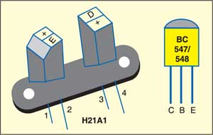
Fig. 1 shows the circuit of the smoke detector, while Fig. 2 shows pin configurations of sensor H21A1 and transistor BC547.

Resistor R1 limits the current through the LED inside the sensor. Normally, the phototransistor inside the sensor is in active state and therefore the base terminal of transistor T1 is at a low potential. Preset VR1 determines the threshold level and resistor R2 provides additional protection to transistor T1 and the sensor unit.

The trigger input (pin 2) of the monostable wired around NE555 (IC2) is pulled high by resistor R3. Normally, when there is no smoke near the the sensor, pin 2 remains high due to conduction of transistor T1 and, as a result, relay RL1 de-energises to switch off the audio/video alarm connected via its normally-opened (N/O) contact. This is indicated by glowing of the red LED (LED1). Resistor R7 limits the current through LED1.
Whenever the sensor detects smoke, the internal phototransistor doesn’t get sufficient light from the internal LED and, as a result, transistor T1 forward biases to make trigger pin 2 of IC2 low. Instantly, LED1 turns off and relay RL1 energises. Freewheeling diode D1 suppresses the counter emf.
Here, the monostable built around IC2 is wired as a missing-link detector. So the relay is energised continuously till the initial input condition (no smoke) is maintained. Components R6 and C2 determine the time-out for the monostable.
Construction & testing
The circuit can be easily assembled on a bread-board or general-purpose PCB. It can be powered by regulated 6V DC. Connect the 230V mains supply wire to the audio/video alarm through the N/O contacts of relay RL1. Connect the sensor to the circuit through the wires and install it at a suitable place convenient to you.
The article was first published in November 2006 and has recently been updated.
Feel interested? Check out other electronics projects.
Dear sir
please kindly furnished us with your best price as describe below
1.Optical smoke and heat detector 851PH,in-54-17:2005
uses:mx digital protocol 516.850.055
Warm regards
Tadaferua Aghogho
How can we increase the sensitivity of smoke detector?