


 NTC thermistors are often the preferred choice for temperature sensing and control in many applications, primarily because of their small package sizes and attractive price-performance ratios. An NTC thermistor’s sensitivity to temperature changes, even in small increments, enables the device to be used in temperature-sensing/control applications. This project for the over-heat detector uses a 10k NTC thermistor.
Circuit and working
The circuit diagram of the overheat detector is shown in Fig. 1. It is built around a negative temperature co-efficient (NTC1), popular dual opamp LM358 (IC1), 12V, 1C/O relay and a few other components.
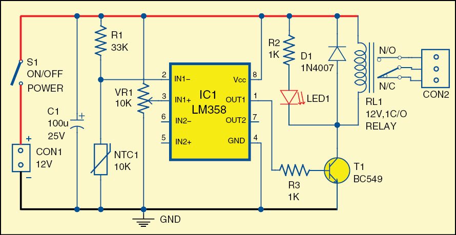
The dual opamp LM358 has been used here for sensing temperature variations near the sensor. At room temperature, thermistor resistance is around 10k. When the temperature increases, thermistor’s resistance becomes low and output of IC1 at its pin 1 becomes high. As a result, the npn transistor conducts and activates the relay.

For testing the circuit, using potmeter VR1, set reference voltage, say, 2V, at pin 3 of IC1. At normal room temperature, voltage at pin 2 of IC1 remains around 2.4V.
On slightly heating NTC1, voltage at pin 2 of IC1 decreases. When this voltage goes below 2V, output of IC1 at pin 1 goes high and relay RL1 energizes to activate the load connected to it.
Construction and testing
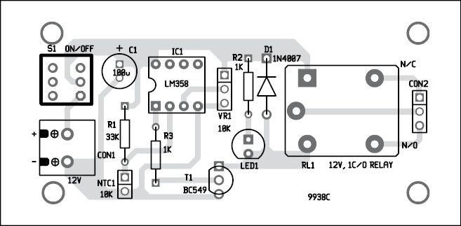
A single-side PCB for the over-heat detector is shown in Fig. 2 and its component layout in Fig. 3. Enclose the PCB in a suitable small box in such a way that the thermistor can be placed near the heating area. Since the thermistor is used as a sensor, better fix it at a spot from where it can sense the temperature. Ensure proper wiring of the circuit to avoid any mistake.

Download PCB and component layout PDFs: click here
Panel-mount the input and output interface and the on/off switch, as required.
Pradeep G. is B.Sc. (Physics) and a regular contributor to international magazines. He is also a small-business owner making school/college projects in South India.
Over-Heat Detector
Is the detector for sale as a kit? or just the pc board?
Termistor play the parts to detect overheating ?
recently, i have one unit of mitsubishi inverter A800.Alarm inverter occured E.GF (earth fault at inverter outer).
After many troubleshoot the alarm, not the main motor or cablr earth pron=ble,.
We use blowwr blow direst to power car area of this invertyer.
Take not the three of suction fan air out and panel ventilation is normal and working ok.
After we blow add this external blowr blow the inverter, alarm E.GF.
Can anyone share with me how to trace out the faulty electronic components detect heat ( i mean is it termistor causing this problem)
Hopefully anyone can give me a guidline to trace out which componwnts affected this heat E.GF alarm.
Regards
Mr. Anderson Ng