


 Pulse counters are widely used in our day-to-day life. Almost all museums and theaters have a visitor counter installed at entry exit to measure the visitor traffic. In industries, counting is done for production control. Market tests too are performed by counting the sold goods.
A pulse counter could be roughly divided into three parts: a pulse source, an electronic device that counts, stores and prepares outputs, and a display to show the accumulated count.

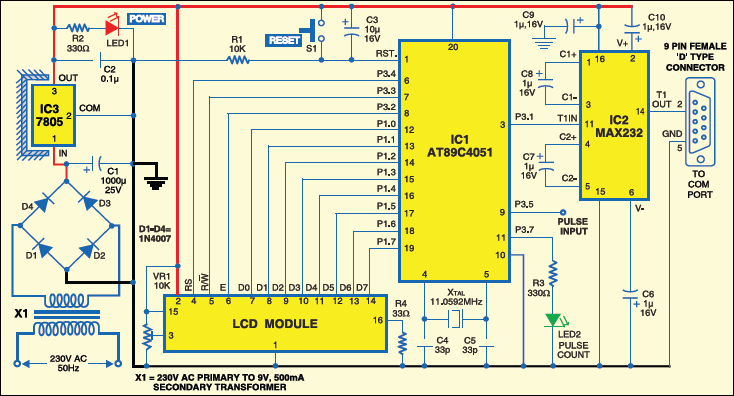
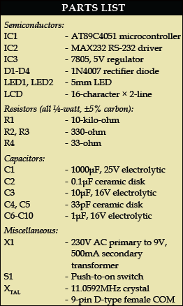
This pulse counter is based on Atmel AT89C4051 microcontroller. TTL-logic-compatible pulses generated by the source are fed to the counter for counting. The AT89C4051 is a low-voltage, high-performance, 8-bit microcontroller with 4 kB of Flash programmable and erasable read-only memory, 128 bytes of RAM, 15 input/ output (I/O) lines, two 16-bit timers/ counters, a five-vector, two-level interrupt architecture, a full-duplex serial port, a precision analogue comparator, on-chip oscillator and clock circuitry.
System clock plays a significant role in operation of the microcontroller. An 11.0592MHz quartz crystal provides basic clock to the microcontroller (IC1) at its pins 4 and 5. Power-on reset is provided by electrolytic capacitor C3 and resistor R1. Switch S1 is used for manual reset.
Port pin P3.5 receives the input pulse and the count is displayed on the LCD as well as hyper terminal of the PC. Pulse reception is indicated by LED2, which is connected to port pin P3.7 of the microcontroller. Port pins P1.0 through P1.7 of the microcontroller are connected to data pins D0 through D7 of the LCD, respectively. Port pins P3.4, P3.3 and P3.2 are connected to register-select RS, read-write R/W and enable E of the LCD, respectively.
The data is sent to the LCD in ASCII format for display. Only the commands are sent in hex form to the LCD. Register-select RS signal is used to distinguish between data (RS=1) and command (RS=0). Using preset VR1, you can control the contrast of the LCD. Resistor R4 limits the current through backlight of the LCD.
Port pin P3.1 of the microcontroller is used to interface with the PC’s hyper terminal through RS-232 interface MAX232 IC (IC2). The microcontroller provides a transmit channel for serial data transfer. Transmit data pin (TXD) is specified at port pin P3.1. The microcontroller is connected to TIN (pin 11) of MAX232. TOUT (pin 14) of IC2 is connected to pin 2 of the COM port connector. The signals provided on these pins are TTL-level and must be boosted and inverted through a MAX232 converter to comply with RS-232 standard.

Hey himanshu how can I contact you
The source code link is broken kindly fix it.
Source code link is not working.
Thank You for your comment. The source folder has been updated. You can download now.