


The circuit described here can be used for controlling a decorative lamp from zero intensity to maximum intensity in a specified time. Typical applications are for controlling Christmas lamps and serial lampsets etc. The brightness of the lamps is controlled by a continuously running ramp voltage generated by a timer.
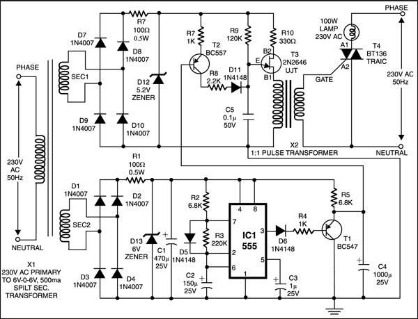
The circuit features a triac (BT136) controlled by pulses from a UJT (unijunction transistor) relaxation oscillator. Pedestal voltage control is employed for controlling the firing angle. Pedestal voltage is derived from,a ramp generator which sets the time period of intensity control.

X1 secondary (sec. 2) provides the power supply for the ramp generator section. The 555 timer circuit is configured as astable multivibrator which provides rectangular pulses having required time period which are converted to a positive going ramp by sweep generator transistor T1. This is coupled to the base of transistor T2. The time period of control can be altered by modifying the sweep generator and 555 timer sections.
X1 is a step-down transformer having two secondaries. Any centre-tapped step-down transformer will serve the purpose. However, it is advisable to have a higher voltage rating (9V or 12V) for X1 secondary (sec. 1) for extended control range.
Zener diode D12 generates the required trapezoidal waveform for the UJT oscillator from the bridge rectifier output. Transistor T2 controls the charging time of capacitor C5, thus providing the pedestal voltage control.
The pulses generated by the UJT oscillator are coupled to the gate of triac through a pulse transformer (X2). A ferrite core transformer with 1:1 ratio can also be used for X2.
Also check IoT based light dimmer.