


 It has almost been 40 years or more and still C language is ruling the world. Also, it has been the first choice of embedded engineers. It is simple to learn and a comfort zone for many who have already learnt it and do not want to switch to a new language. So let us develop applications on Raspberry Pi using this language.
For electronics enthusiasts, the main area of interest is the general-purpose input/output (GPIO) port of Raspberry Pi. It is a generic pin on a chip and its status (that is, input/output (I/O) or logic levels) can be controlled/programmed through software. GPIO pins have great importance in the embedded world as you can interface lower-level peripherals and control them by manipulating at bit level.
Being a hardware resource, GPIOs require assembly languages (which are specific to that controller) to control them. If one wants to use a higher-level programming language to control them then additional header/library files are needed, which will map functionality from higher level languages to Assembly language.

Raspberry Pi supports a number of programming languages such as C, C++, Ruby, Perl, Python, Java and PHP but, to access GPIO, all of them require additional libraries.
Due to availability of cross compilers for C, it is possible to program microcontrollers with different architectures without learning individual Assembly languages. Accessing I/Os, bit manipulations and direct hardware control is possible in C with simplicity like higher level languages at the same time.
Raspberry Pi is not an exception in the world of embedded systems. Thanks to Gordon Henderson who developed C library (called WiringPi) for Raspberry Pi to facilitate its GPIO access using C language.
About GPIOs of Raspberry Pi
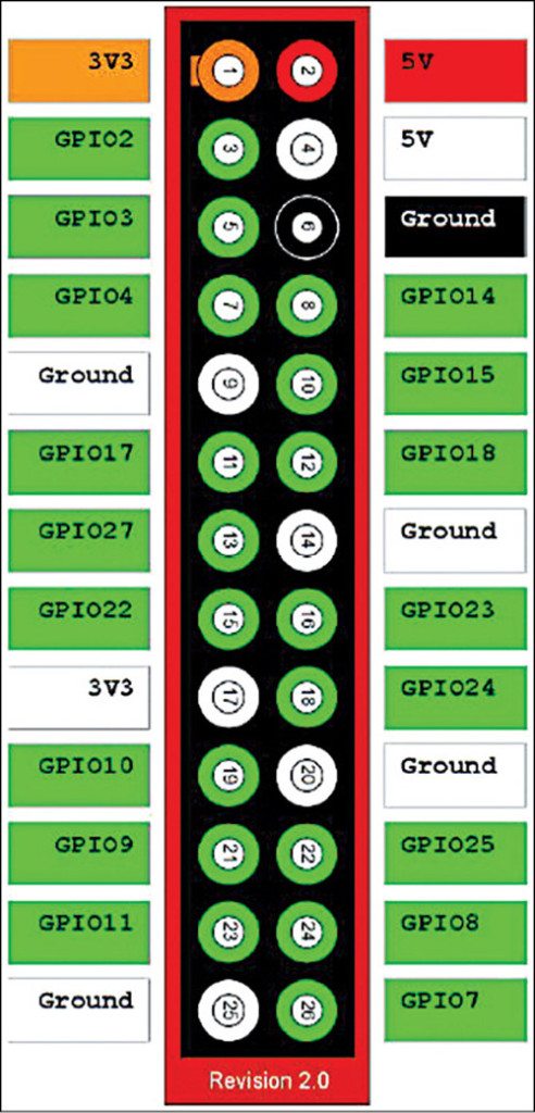
The Raspberry Pi has a 26-pin GPIO connector. There are eight GPIO pins which can be programmed as either digital outputs or inputs. One of these pins can be designated for PWM output too.
Additionally, there is a 2-wire I2C interface and a 4-wire SPI interface. The I2C and SPI interfaces can also be used as GPIO pins when they are not being used in their bus modes, and the UART pins can also be used if you reboot with the serial console disabled. Fig. 1 shows the Raspberry Pi header.
Note here that pins in white colour are unused pins. These pins are reserved for future use and should not be connected to at this point in time
Getting started with WiringPi
WiringPi is an Arduino wiring-like library (part of the Arduino software package called Wiring that handles input and output for the Arduino) written in C and released under the GNU LGPLv3 licence, which is usable from C and C++ and many other languages with suitable wrappers.
To develop C applications with WiringPi a compiler is needed. Usually, GNU compiler collection (GCC) is already built in Linux distribution that runs on Raspberry Pi.
WiringPi library needs to be installed on Raspberry Pi. To download and install the library follow guidelines on http://wiringpi.com/download-and-install/
Once the library is installed, we are all set to write C program on Raspberry Pi. Before writing it, one needs to understand how to address/refer GPIO pins.
Referring to pins on the expansion header
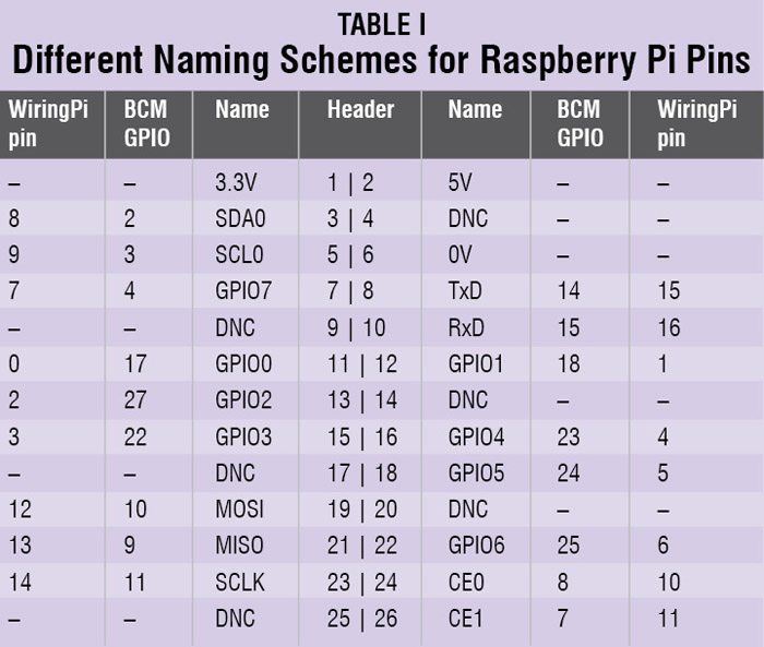
Any signal (or pin) can be referred to in program in three ways:
1. Broadcom signal names on the SoC (BCM GPIO NUMBER), for example, GPIO 4
2. Pin names on the Raspberry Pi board headers (PIN NUMBER), for example, PIN 7 or PI-07
3. Names used in the WiringPi library (WIRING PI PIN), for example, 7
Table I shows different names for each Raspberry pin.
In this article, we are going to use third scheme (WiringPi pin numbers, that is, first column from Table I).
Project 1: Blinking the Led using Wiring Pi C
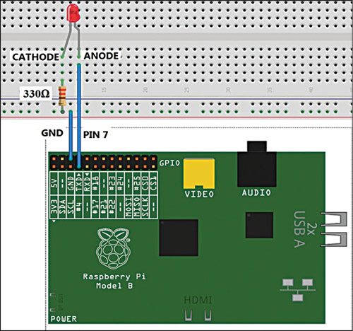
In this project, we will access the GPIO pin of Raspberry Pi and control it for blinking an LED using the WiringPi C. Connect the LED to pin number 7 (BCM GPIO 4) of Raspberry Pi as shown in Fig. 2.
Software
Start with C programming and open LxTerminal to create new C file by using the following command:
$ touch led.c
Then start nano text editor as:
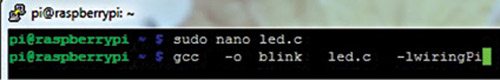
$ sudo nano led.c
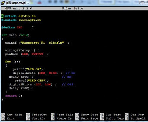
Type the following C code or copy and paste it to the file as shown in Fig. 3:
————led.c——————-
#include
#include
#define LED 7
int main (void)
{
printf (“Raspberry Pi blink\n”) ;
wiringPiSetup () ;
pinMode (LED, OUTPUT) ;
for (;;)
{
printf(“LED ON”);
digitalWrite (LED, HIGH) ; // On
delay (500) ; // mS
printf(“LED OFF”);
digitalWrite (LED, LOW) ; // Off
delay (500) ;
}
return 0;
}
Once you are finished, press Ctrl + O to save and then Ctrl + X to exit from the nano editor.
Now, compile the program by typing the following command as shown in Fig. 4
$ gcc –o blink led.c -lwiringPi
[/stextbox]In the above compilation command, the word after -o denotes name of output file. At the end, we need to add -lwiringPi to notify the compiler that we are using library WiringPi (note, only P is capital in the last word).
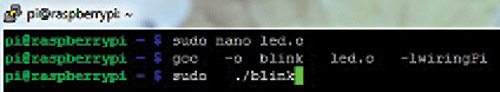
Now run the program using the following command as shown in Fig. 5:
$ sudo ./blink
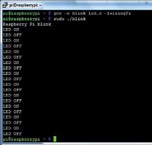
In the above execution command, dot slash is followed by output filename that we specified in the compilation command. After running the program, LED will start blinking and the LED ON and LED OFF will be displayed on the terminal of Raspberry Pi as shown in Fig. 6.
Download Source Code: Click Here
You can observe the output on screen and see LED blinking according to the program. You can also change the delay and Raspberry Pi pin as per your needs.
Functions of Wiring Pi library used in led.c
WiringPiSetup(void). This initialises the WiringPi system and assumes that the calling program is going to use the wiringPi pin numbering scheme. This function must be called at the start of your program.
void pinMode (int pin, int mode). The pin number is obtained from the pins table. This sets the mode of a pin to either INPUT, OUTPUT or PWM_OUTPUT.
void digitalWrite (int pin, int value). Writes the value HIGH or LOW (1 or 0) to the given pin which must have been previously set as an output using pinMode( ) function.
void delay (unsigned int howLong). This causes program execution to pause for at least howLong milliseconds. Due to the multi-tasking nature of Linux, it could be longer. Note that the maximum delay is an unsigned 32-bit integer or approximately 49 days.
Project 2: Seven-segment counter display using Wiring Pi C
In this project, we will display the numbers from 0 to 9 in seven-segment display using Wiring Pi C.
Circuit
Connect the seven-segment display (common anode) to the pins of Raspberry Pi as shown in Fig. 7. Connect the seven-segment display to the Raspberry Pi pins as shown in Table II.
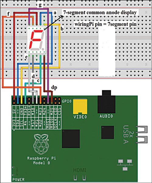
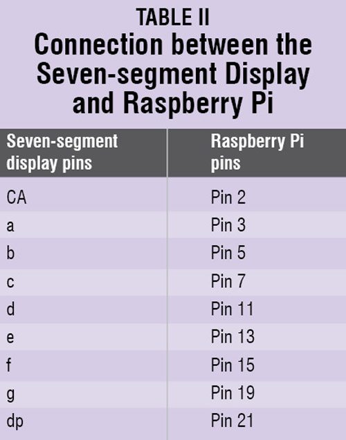 Note. Add 330- or 470-ohm resistors for each connection (not shown in the Fig. 7 to avoid complexity).
Software
Open LxTerminal and create a new C file using following command:
$ touch counter.c
Start nano text editor as:
$ sudo nano counter.c
Type below C code or paste it to the LxTerminal.
————-counter.c————
#include
#include
//GPIO to seven-segment pins
a,b,c,d,e,f,g,dp
//these are wiring Pi pin numbers
unsigned int
gpio[8]={8,9,7,0,2,3,12,13};
unsigned int b[8]; // for bit values
of one seven-segment digit
//seven-segment code for 0 to 9
digits
unsigned int ssc[10]={0xc0,0xF9,0xa4,
0xb0,0x99,0x92,
0x82,0xf8,0x80,0x90};
void seg_count(int);
int main()
{
int i,b;
printf(“counter\n”);
if(wiringPiSetup () == -1)
//initialisation
return 1 ;
for(i=0;i<=7;i++)
pinMode (gpio[i], OUTPUT) ;
// pin mode set to output
while(1)
{
for(i=0;i<=9;i++)
{
seg_count(i);
delay(1000);
}
}
return 0;
}
void seg_count (int x)
{
int i;
//separating bits from digit x
for(i=0;i<=7;i++) b[i]=(ssc[x]>>i)& 0x01;
printf (“Raspberry Pi seven segment
display %d\n”,x) ;
for (i=0;i<=7;i++) // setting
GPIO pins as per seven seg code
digitalWrite(gpio[i],b[i]) ;
}
Once you are finished, press Ctrl + O to save and then Ctrl + X to exit from the nano editor.
Now compile the code:
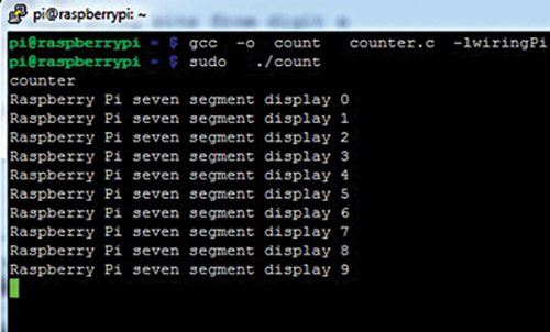
$ gcc -o count counter.c -lwiringPi
and then execute it as shown in Fig. 8.
$ sudo ./count
You will see different numbers displayed in a sequence and the terminal window will display messages as shown in Fig. 8. You can abort the execution by pressing Ctrl+Z.
The author is pursuing M.Tech in electronics at Walchand College of Engineering, Sangli, Maharashtra