


Presented here is a RF controlled aircraft project based on Arduino and 433MHz RF modules controlling a brushless DC motor and three servo motors. It comprises an Arduino-based remote control at the transmitter’s end and an Arduino-based aircraft at the receiver’s end. The aim of this project is to develop a 4-channel wireless control system.
Controlling multiple servo motors using XBee RF modules is very sophisticated and robust but a bit costlier. For cheaper solution, we used a pair of simple 433MHz RF transmitter and receiver modules.
RF controlled aircraft circuit
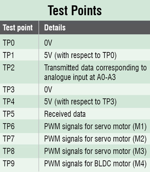

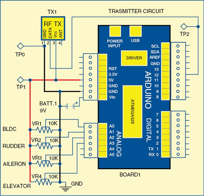
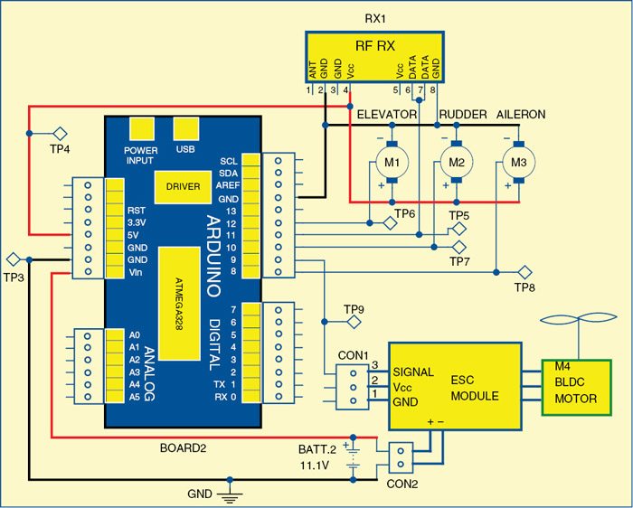
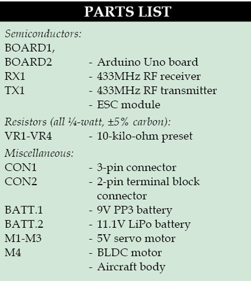
Fig. 1 shows the circuit diagram of an RF controlled aircraft’s transmitter side and Fig. 2 shows the circuit diagram of the receiver side. The circuits are built around Arduino Uno (board1 and board2), a pair of 433MHz RF modules (TX1 and RX1), ESC (electronic speed controller) module, three servo motors (M1-M3), a BLDC motor (M4) and a few other components.
The transmitter’s side is driven by a 9V PP3 battery and the receiver’s side by an 11.1V LiPo battery, which is used to power the brushless DC motor (BLDC motor) through the ESC module.
The Arduino board1 receives power supply from the 9V PP3 battery and Arduino board2 from the 11.1V battery at their respective Vin input pins.
There are four potentiometers on the transmitter’s side which are used for sending different control signals to the receiver’s side through the RF modules. The control signals received by the receiver are processed by the microcontroller in the Arduino, which in turn controls the BLDC motor, the servo motors for rudder, aileron and elevator of the aircraft.
Arduino Uno board
Arduino is an open source electronics prototyping platform based on flexible, easy-to-use hardware and software. It is intended for artists, designers, hobbyists and anyone interested in creating interactive objects or environments.
Arduino Uno is a board based on ATmega328 microcontroller. It comprises 14 digital input/output (I/O) pins, six analogue inputs, a USB connection for programming the on-board microcontroller, power jack, an ICSP header and a reset button.
It is operated with a 16MHz crystal oscillator and contains everything needed to support the microcontroller. It is very easy to use as the user simply needs to connect it to a computer with a USB cable, or power it with an AC-to-DC adaptor or battery to get it started. The microcontroller on the board is programmed using Arduino programming language and Arduino development environment.
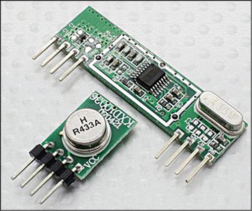
433MHz RF modules
These are inexpensive radios that operate at 433MHz frequency (refer Fig. 3). These radios are available in a separate transmitter and receiver or a single transceiver model. The operating voltage for transmitter is from 1.5V to 12V and for the receiver is from 3V to 5V. The range of transmission is 30m to 150m depending on the voltage supply and the type of module used.
Transmitter’s side
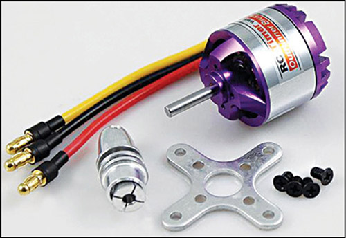
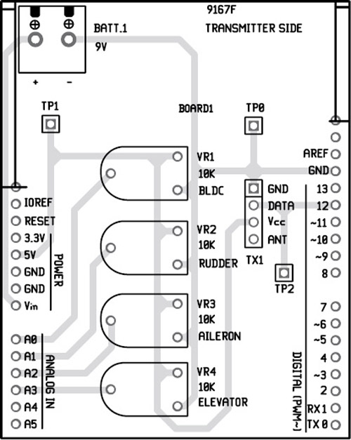
Pin 12 of board1 is connected with data pin 2 of RF transmitter (TX1). Pin A0 through A3 of board1 are connected with four 10k presets (VR1 throughVR4). VR1, VR2, VR3 and VR4 are used to control BLDC (refer Fig. 4), rudder, aileron and elevator, respectively.
Receiver’s side
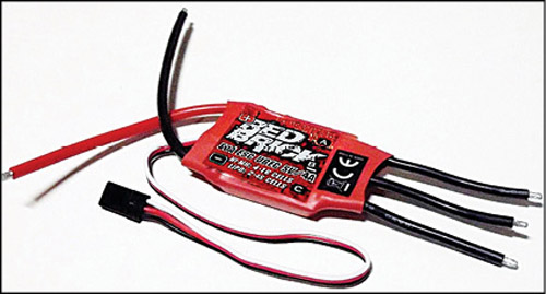
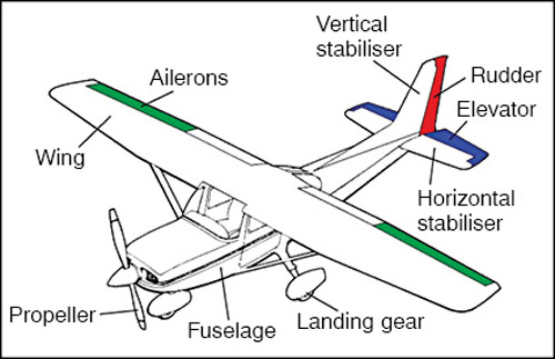
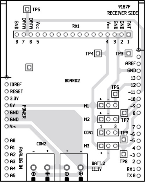
Pin 11 of board2 is connected with data pins (6 and 7) of RF receiver (RX1). The pins 12, 10, 8 and 9 of the board are connected with the signal pin of M1 (elevator), M2 (rudder), M3 (aileron) servo motors and ESC module (refer Fig. 5), respectively. Some of the main body parts of a typical RC aircraft are shown in Fig. 6.
BLDC motor is used as the propeller system of the aircraft. The propeller or airscrew converts rotary motion from the motor to provide propulsive force. It is the most important part of the aircraft. The propeller is mounted on the front side of the aircraft.
A rudder is used to steer the aircraft that moves through the air medium, controlling the direction in which the aircraft is pointing. It is a flat plane or sheet of material attached with hinges to the craft’s stern, tail or after end.
An aileron is a hinged flight-control surface usually attached to the trailing edge of each wing of an aircraft. Ailerons are used in pairs to control the aircraft in roll, or movement around the aircraft’s longitudinal axis.
Elevators are flight control surfaces, usually at the rear of an aircraft, which control the aircraft’s longitudinal altitude. The position of the elevator controls whether the nose of the airplane is pointing up or down and thus moving up or down. The elevators are usually hinged to a fixed or adjustable rear surface.
Input supply wire of ESC is connected with an 11.1V battery. Three output wires of ESC are connected with three phase inputs of BLDC motor (M4).
Software
The software of this project is written in Arduino programming language. The Arduino UNO is programmed using Arduino IDE software. ATmega328 on Arduino UNO comes with a boot loader that allows you to upload a new code to it without the use of an external hardware programmer. It communicates using the STK500 protocol.
You can also bypass the boot loader and program the microcontroller through in-circuit serial programming (ICSP) header, but using boot loader programming is quick and easy. Select the correct board from ‘Tools → Board’ menu in Arduino IDE and burn the program (sketch) through a standard USB port in the computer.
Add library ‘SoftwareServo’ in the libraries folder (arduino-0022\libraries) of Arduino IDE before compiling the sketch.
We have used red brick ESC module. If you use any other ESC module, you may be required to modify the delays in the code accordingly.
Construction and testing
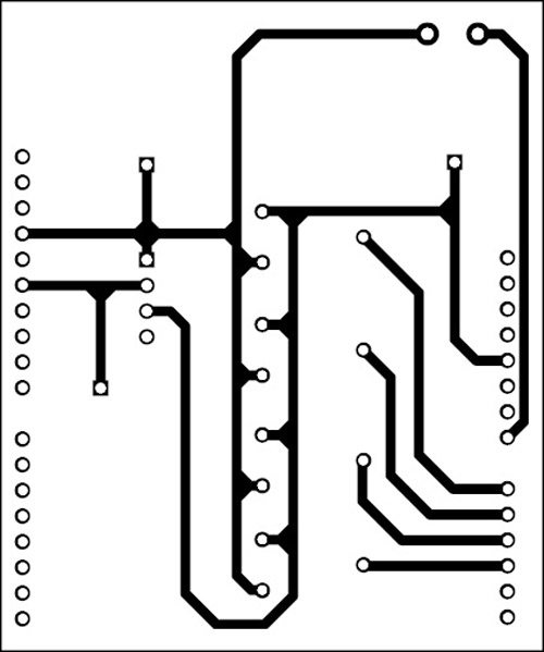
A single-side PCB for the RF controlled aircraft transmitter circuit is shown in Fig. 7 and its component layout in Fig. 8. The PCB for the receiver circuit is shown in Fig. 9 and its component layout in Fig. 10.
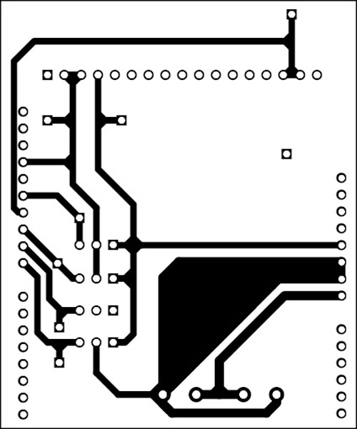
Download the PCB layout & Component Layout PDFs: Click Here
Download Source Code: Click Here
PCBs of transmitter and receiver are in the form of shields, so mount these PCBs on top of the respective Arduino UNO board. Connect 9V battery to the transmitter’s side and 11.1V battery to the receiver’s side. Check the working of BLDC motor by varying VR1, servo motor M1 using VR4, servo motor M2 using VR2 and servo motor M3 using VR3. If there is any problem, verify the test points given in the table. Once this is done, it is time to build the body of the aircraft.
Building a remote-controlled (RC) aircraft requires some basic skills and creativity. There are some rich tutorials available on the Internet.
[stextbox id=”info” caption=”Some information to build your own RC aircraft can be found from these links:”]http://www.easyrc.com/airplanes/
http://rcvehicles.about.com/od/diyaircraft/
http://www.stenulson.net/rcflight/rcflight.htm[/stextbox]
You can either build the body of the aircraft by yourself or get it from an electronics spare parts shop. The receiver PCB along with the 11.1V battery should be mounted properly on the aircraft. Now, your RF controlled aircraft is ready to fly.
The aircraft can be launched by gathering speed on a long runway or by launching with the use of hands by literally throwing it into the air. In the first case, as soon as your plane builds up enough speed and catches the wind, it will lift from the ground. But note that if the road surface is uneven, or it is covered with grass, your plane might not be able to gather the necessary speed for takeoff. At this point, you should opt for a hand launch.
Since the aircraft is controlled by a remote control it has a finite range. If your plane gets too far (either vertically or horizontally) from the transmitter in your hand, it might lose power. This will send your plane plummeting back to the ground. The usual way to fly it is in a circular pattern above your head.
After assembling all the parts, switch on both the transmitter and receiver circuits. Slowly vary VR1 to increase the speed of the BLDC motor (propeller). Once it takes off above the ground, vary VR2, VR3 and VR4 and observe the flight pattern. Ensure that it does not go beyond 100m distance from the transmitter in your hand. To bring it back to the ground, reduce the speed by varying VR1.
Feel interested? Check out other electronics projects.
Source code shows error..
Kindly elaborate your query.
replace Wprogram in file SoftwareServo with Arduino before adding this file in ardiuno ide
the time of servomotor responding is too much about 2 seconds its too much to control an airplane
yhks
on transmitter.ino compile and upload went OK but on receiver got the error :
Arduino: 1.6.9 (Windows 7), Board: “Arduino Nano, ATmega328”
In file included from C:\Users\Shadow\Desktop\RF-Controlled Aircraft\RF-Controlled Aircraft\Source code (4 channel remote)\receiver\receiver.ino:1:0:
D:\Program Files (x86)\Arduino\libraries\SoftwareServo/SoftwareServo.h:4:22: fatal error: WProgram.h: No such file or directory
#include
^
compilation terminated.
exit status 1
Error compiling for board Arduino Nano.
This report would have more information with
“Show verbose output during compilation”
option enabled in File -> Preferences.
please help to solve the problem , i included the software servo folder in library folder
can i use some other microcontroller apart from arduino for this project?
if yes which one do you suggest?
can i use some other microcontroller apart from arduino for this project?
if yes then which one do you suggest?
I copied the softwareServo file to the following location D:\software\arduino\arduino-1.8.3\libraries
Yet it shows two errors for transmitter and receiver code .
D:\PROJECT\esc\RF-Controlled Aircraft\Source code (4 channel remote)\transmitter\transmitter.ino:1:25: fatal error: VirtualWire.h: No such file or directory
#include
D:\software\arduino\arduino-1.8.3\libraries\SoftwareServo/SoftwareServo.h:4:22: fatal error: WProgram.h: No such file or directory
#include
how can i solve this.
yes , same for me . Can you please help us EFY Team ?
replace text “WProgram.h” in library SoftwareServo.h with “Arduino.h”
you must replace text “WProgram.h” with “Arduino.h” in SoftwareServo.h library
can we reolace the potontionmeter with joystick help please thks
The author Somnath Bera replies:
Yes, very much. In fact, joystick is the right thing for this type of maneuvering. Because I did not have joystick at that time [This is a pretty old project of mine]. I used four separate Pots [Potentiometers]
But you have to group them separately and selectively. Each Joystick is a pair of pots operate on horizontal planes – XX plane and YY plane. Normally Radder and BLDC can group together [If Radder operates the Nose goes up or down and the speed needs to go up or down]
Same way Aileron & Elevator can group together in the other joystick to maneuver the left-right movement of the aircraft.
Efy we need you, the rceiever code uploading not responding