


 Security is a prime concern in our day-to-day life. And access control system forms a vital link in a security chain. The microcontroller based digital lock presented here is a secured room access system that allows only authorized persons to access a restricted area. When someone tries to enter the restricted area by entering invalid passwords continuously, the system locks down and can be unlocked only by the master user.
The system comprises a small electronic unit with a numeric keypad, which is fixed outside the entry door to control a solenoid operated lock. When an authorized person enters a predetermined number i.e. the password via the keypad, the relay energizes for a limited time to unlock the solenoid operated lock, so door can be pushed/pulled open. At the end of the preset delay, the relay de-energizes and the door gets locked again. A prompt message is displayed on the LCD module.
Secured room access system circuit description
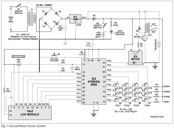
The system uses a compact circuitry built around AVR microcontroller ATmega8535. The ATmega8535 is a low power CMOS 8-bit microcontroller based on the AVR-enhanced RISC architecture. It provides the following features: 8 kB of in-system programmable Flash memory with read-while-write capabilities, 512-byte EEPROM, 512-byte SRAM, 32 general purpose I/O lines, 32 general-purpose working registers, three flexible timer/counters with compare modes, and internal and external interrupts. The built-in power-on-reset circuitry of the microcontroller eliminates the need for external power-on-reset circuit.
Switch S3 is used to reset the system, which is accessible only to the master user. Port D (PD0 through PD7) is interfaced with the numeric keypad. Port C is interfaced with a 16×2 line LCD. Four pins (PC4 through PC7) of Port C are used as data lines for the LCD module and three lines (PC0 through PC2) are used for controlling the LCD. Pin 40 (PAO) of port A is connected to the relay driver circuit through opto-coupler MCT2E (IC3) and transistor T1.
When port pin PA0 goes high, the internal transistor of IC3 drives transistor T1 into saturation and relay RL1 energizes. As the solenoid valve is connected through normally-closed (N/C) contact of the relay, the solenoid coil de-energizes and the gate is locked. An 8MHz crystal is used with two 22 pF capacitors for providing clock. Preset VR1 is used to adjust the contrast of the LCD.
The 230V, 50Hz AC mains is stepped down by transformer X1 to deliver a secondary output of 9V, 500 mA. The transformer output is rectified by a full-wave bridge rectifier comprising diodes D1 through D4, filtered by capacitor C1 and regulated by IC 7806 (IC1). Use adequate heat-sink for 7806 as the solenoid draws a high current. LED1 glows when power is ‘on’ and resistor R6 acts as the current limiter.
A 16-key numeric keypad for password entry is connected to the microcontroller. The keypad is also used for password change and application of master password when required. To economize the use of I/O pins, we have used here only eight pins for scanning and sensing 16 keys.
</center
Secured room access system operation
The keypad is arranged in a 4×4 matrix. There are four scan lines/pins, which are set in output mode, and four sense keys, which are used as input lines to the microcontroller.
At a small time interval, the microcontroller sets one of the four scan lines as low and the other three scan lines as high. Then it checks for the status of sense lines one by one at the intersection of a specific scan line and sense line to find out if any key has been pressed.
Similarly, after a small time interval, the next scan line is made low and remaining three scan lines are taken high, and again all three sense lines are checked for low level. This way the microcontroller checks which of the 16 keys is pressed.
Due to the high speed of the microcontroller, the status of different keys is checked in less than 100 ms and a key press is detected and identified. As the keys are pressed manually by the user, this delay of 100 ms is not noticeable. The net result is that you save on I/O pins of the microcontroller by sacrificing almost nothing.
When a person wants to enter the room, he enters the 6-digit password, say ‘123456.’ If the password matches successfully, the gate is unlocked for 15 seconds.
If you want to change the user password (123456) and enter the master password ‘291279,’ the system will ask you to change the user password. On successfully entering the password, pin A0 of port A becomes high for 15 seconds, because of which transistor T1 starts conducting through the emitter of the opto-coupler and the relay energizes. The connection between the solenoid lock and the power supply is broken and the door is unlocked for 15 seconds.
An actual-size, single-side PCB and its component layout view for secured room access system is provided in the PDF.
Download PCB and component layout PDFs: click here
Software
The software for the AVR microcontroller is written in ‘C’ language and compiled using Code Vision AVR ‘C’ compiler. Since this compiler does not have library functions for the keypad, place ‘kbd.h’ file in the INC folder of the installation folder and ‘kbd.lib’ in the LIB folder of ‘cvavr’ folder. This file is included in the program and the same can be used.
Download source code: click here
</center

I LIKE THE ELECTRONICS WORK .SO ,I WANT JOIN YOUR ELECTRONICS COMMUNITY. R?