


Here is a sleep-switch circuit that can be easily converted into a wake-up timer. A dual-mode time setting makes the system versatile. The circuit is low-cost and can function as a precise timer.
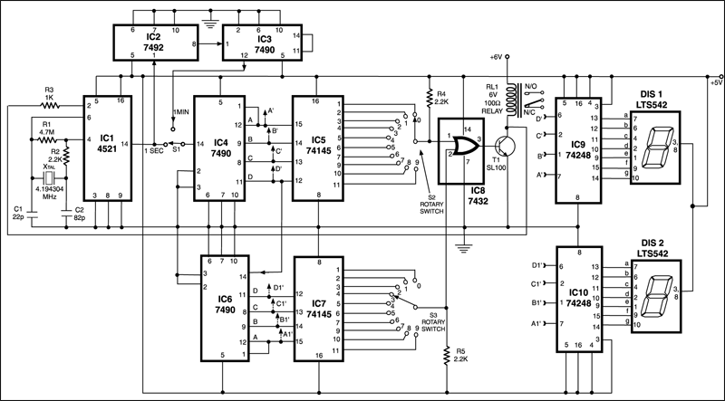
The clock beat produced by IC1 is a sharp 1Hz square wave signal having a duty cycle of 50 per cent. This is achieved by using a 4.194304 MHz crystal in combination with discrete components around it. The 1Hz output of IC 1 is connected to IC2 as well as one of the terminals of switch S1. IC2 is configured as divide by- 6 counter while IC3 further divides the output of IC2 by ten to produce one-minute output at its pin 12. This is brought to the second terminal of two way switch S1 to help select either the minutes’ or the ‘seconds’ mode of operation for IC4.

The decade counter IC4 provides binary output as it counts up the input pulses and IC5 decodes/converts them to 1-of-10 outputs (units). Similarly, the IC6-IC7 pair provides tens output since IC6 clock input pin is connected to D output pin of IC4.
Rotary switches S2 and S3 can be set to select any time between either 0 to 99 seconds or 0 to 99 minutes, depending upon the position of mode switch S1. Switches S2 and S3 could also be replaced by thumb-wheel type switches or 10-position DIP switches with one of their side terminals shorted together to serve as a pole. Please note that IC5 and IC7 (74145) have active low outputs.

The outputs from switches S2 and S3 are input to a two-input OR gate inside IC8 (7432) to obtain active low output on completion of the set time delay to deactivate relay RL1 through relay driver transistor T1 (normally conducting) when set time is reached. When transistor T1 cuts off, its collector goes high to reset oscillator IC1, and thus count at output of IC4 and IC6 gets locked. For resetting or restarting, the power supply to the circuit should be switched off and then switched on again.
The BCD outputs of IC4 and IC6 are converted to seven-segment outputs by IC9 and IC10 to drive the units and tens displays respectively for indicating elapsed time continuously. The relay contacts (normally open and normally closed) can be suitably used to energise or de-energise an alarm after the preset delay. It can thus be used as wake-up alarm or sleep timer.
If you want to de-energise the relay, say after 30 minutes, then set switch S1 to minutes mode, S2 to 0 and S3 to 3, and then switch on the supply to the circuit. After 30 minutes the outputs at poles of switches S2 and S3 will go low and so also the output of OR gate (IC8). As a result, transistor T1 will be cut-off to de-energise the relay.
One can easily add 0-99 hours capability by cascading two counters similar to the minutes counter section comprising IC2 and IC3. Input clock for hours counter would be the minutes clock available at pin 12 of IC3.
