


A good number of circuits which turn off the power to the load on mains failure have already appeared in EFY. This circuit is different because it consumes no power when the load is off. Further, the circuit is completely solid state as it does not use any relay or other electromechanical devices.
Here resistor R1, diode D1, capacitor C1 and zener D2 are used to develop a mains-derived 9V DC supply which can be fed to the triac gate. Switches S1 and S2 are used to accomplish ‘off ’ and ‘on’ operations respectively.
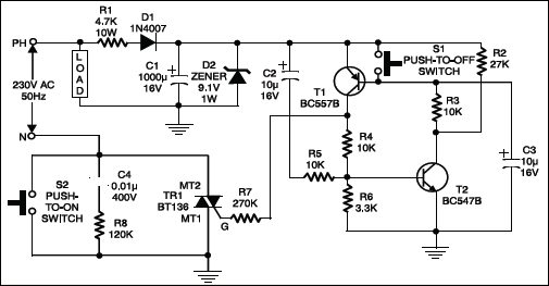
When switch S2 is momentarily depressed the neutral line gets extended to MT1 of triac TR1. This in turn makes the DC voltage available to the transistor circuit. Capacitor C2 and resistor R5 provide the initial base drive to transistor T2 at power-on. By the time capacitor C2 is fully charged, transistor T1 is driven into saturation via transistor T2 and resistor R3.
The collector of transistor T1 is connected to the base of transistor T2 through resistor R4, and collector of transistor T2 is connected to base of transistor T1 via resistor R3, i.e. there exists a mutual symbiosis between transistors T1 and T2. As long as transistor T1 is on, it provides the necessary gate current to the triac through resistor R7. Capacitor C3 prevents false operation of the circuit.
The load can be switched off either by pressing switch S1 or by turning off the power to the circuit. When switch S1 is pressed, transistor T1 is no more in saturation and thus it turns off the triac and the load. Since the rectifier circuit cannot get neutral line when the triac is off, it consumes absolutely no power when then load is off.
The idea can be suitably adopted for timer applications where the power to the timer circuit needs to be turned off after the set time delay. An opto-coupler can replace switch S1 for using the output of a low-voltage control circuit for switching off.
