


 Dual-tone multiple-frequency (DTMF) receiver IC is commonly used in telephone equipment. One common DTMF receiver is Holtek HT9170 used in electronic communication circuits. The Holtek HT9170 series comprises DTMF receivers integrated with digital decoder and band split filter functions.
All HT9170 series ICs use digital counting techniques to detect and decode all the 16 DTMF tone pairs into a 4-bit code output. This telephone-operated calling circuit is very helpful for doctors in calling the patients, in banks and in various other situations where persons have to be called or signalled. When you need to call a person amongst many standing outside your cabin, just lift the telephone handset off the cradle and press the respective number. The number of the person called will be displayed and a bell will sound to inform the person that it is his turn. The circuit can also be used in quiz contests and by visually or hearing impaired people. It can be used to call a maximum of nine different persons.
Circuit with explanation
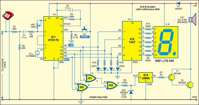
The circuit is built around DTMF receiver IC HT9170, BCD-to-7-segment decoder/driver 7447, quad 2-input OR gate andcommon-anode display. Simple melody generator IC UM66 is used to produce melody sound in the loudspeaker through Darlington-pair transistors (T1 and T2). The tone pair DTMF generated by pressing the telephone key is converted into binary values internally in the IC. The binary values are indicated by the glowing of LEDs at the output of IC1.
The output of IC1 is connected to:
1. LEDs connected via resistors R15 through R18 at pins 11 through 14, respectively. LED1 indicates the LSB and LED4 indicates the MSB.
2. BCD-to-7-segment decoder driver 7447, whose outputs are connected to the common-anode display for displaying the pressed number on the telephone connected in parallel to the circuit.
3. Gates N1 and N2 to activate the call bell.
Calling system circuit working
Here is how the circuit works: Connect the telephone and the circuit in parallel to the telephone line. Connect 6V to the circuit. When you press switch S1, DIS1 shows ‘0.’ Lift the handset off the cradle and dial a number, say, ‘1.’ The output of IC1 becomes A3A2A1A0 = 0001. LED1 glows, the display shows ‘1’ and the call bell sounds.
To stop the call bell, put the receiver on the cradle and press switch S1 momentarily. Now DIS1 shows ‘0’ and LED1 stops glowing. For calling other numbers, follow the same procedure: Lift the handset off the cradle and press the desired number (0 through 9). The respective LED will glow, the number will be displayed on DIS1 and the call bell will sound. Now put the handset on the cradle and press S1 momentarily to stop the call bell.
Looking for more projects? Here they are

Is This project used in Automation ?