


A time controlled switch is an automatic timer switch that turns an appliance ‘on’ for the desired time duration. After the preset time duration, the timer automatically switches off, disconnecting the appliance from the power supply. The time duration for which the appliance should be ‘on’ can be set from 1 to 99 minutes.
This switch obviates the need to continuously monitor the appliance—an advantage over the manual switch. It can be used to switch on or switch off any electrical home appliance at a predetermined time. Switching an appliance on or off in a timely manner increases the life of the appliance and also saves power consumption.
The switch also finds industrial applications, where the machines which control the processes can be run for the desired time.

Time controlled switch circuit
Fig. 1 shows the circuit of the time controlled switch using PIC16F72 microcontroller. It comprises microcontroller PIC16F72 (IC1), regulator 7805 (IC2), two 7-segment displays (LTS542) and a few discrete components.
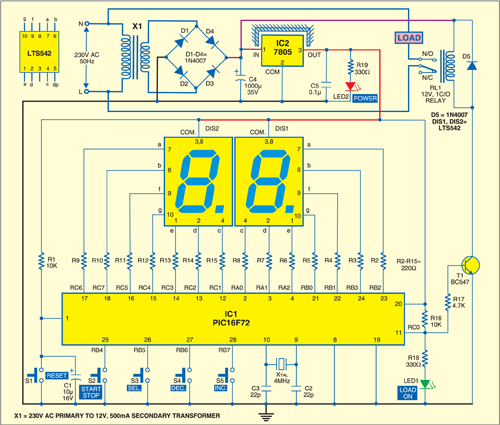
Microcontroller PIC16F72 is the heart of this time controlled switch. It is an 8-bit, low-cost, high-performance, flash microcontroller. Its key features are 2 kB of flash program memory, 128 bytes of RAM, eight interrupts, three input/output (I/O) ports, three timers and a five-channel 8-bit analogue-to-digital converter (ADC). There are 22 I/O pins, which are user-configurable for input/output on pin-to-pin basis. Architecture is RISC, and there are only 35 powerful instructions.
System clock plays a significant role in operation of the microcontroller. A 4MHz quartz crystal connected between pins 9 and 10 provides the basic clock to the microcontroller (IC1).
Two 7-segment displays (DIS1 and DIS2) are used to display the time in minutes. Port pins RB2, RB3, RA0, RA1, RA2, RB1 and RB0 are connected to segment pins ‘a’ through ‘g’ of display DIS1, respectively. Ports pin RC6, RC7, RC1, RC2, RC3, RC5 and RC4 are connected to segment pins ‘a’ through ‘g’ of display DIS2, respectively.
Switches S2 (start/stop), S3 (select), S4 (decrement) and S5 (increment) are connected to port pins RB4 through RB7 of the microcontroller, respectively. Port pin RC0 of the microcontroller is used to control relay RL1 with the help of transistor T1. When port pin RC0 is high, transistor T1 drives into saturation and 12V-relay RL1 energises to connect the load to power supply. Diode D5 acts as a free-wheeling diode.
Circuit Operation
To derive the power supply for the circuit, the 230V, 50Hz AC mains is stepped down by transformer X1 to deliver a secondary output of 12V, 500mA. The transformer output is rectified by a full-wave rectifier comprising diodes D1 through D4, filtered by capacitor C4 and regulated by IC 7805 (IC2). Capacitor C5 is used to bypass the ripples present in the regulated supply. LED2 gives power-‘on’ indication. Resistor R19 limits the current through LED2. Switch S1 is used for manual reset.
Set the time using switch S4 for decrement and switch S5 for increment. The time is indicated on 7-segment displays DIS1 and DIS2. To start timing count-down, press start/stop switch S2. Relay RL1 energises to switch on the appliance and LED1 glows. If you press start/stop switch S2 again, the count-down process will stop and relay RL1 de-energise to switch the appliance off.
Construction and working
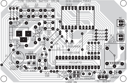
A single-side PCB for the microcontroller-based time controlled switch is shown in Fig. 2 and its component layout in Fig. 3.
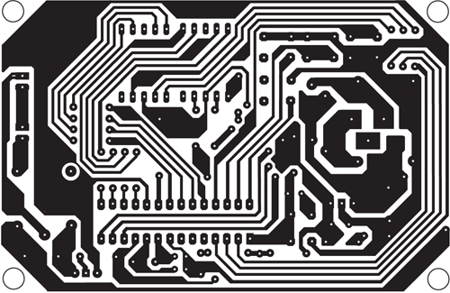
Download PCB and component layout PDFs: click here
Assemble the circuit on a PCB to minimise time and assembly errors. Carefully assemble the components and double-check for any overlooked error. Use an IC base for microcontroller. Before inserting the IC, check the supply voltage.
The time controlled switch works in two modes: setting mode (to set the time from 1 to 99 minutes) and working mode (to drive the load for the desired time as per the setting). The modes can be changed using switch S3. When LED1 glows, it indicates that the system is in working mode. If LED1 is off, the system is in setting mode.
Setting mode
By default, when the microcontroller is powered up, it is in setting mode. In this mode, one of the two 7-segment displays should blink with a random digit, say, 6. You can change the blinking digit to any digit from 0 through 9 using decrement switch S4 or increment switch S5. You can also shift the blinking digit from DIS1 to DIS2 or vice-versa using switch S3. Thus the desired time can be set using switches S3, S4 and S5.
After setting the desired time, press start/stop switch S2 to switch from setting mode to working mode. The appliance will turn on for the preset time unless you press switch S2 again to stop the operation in between.
Working mode
When the microcontroller is powered up, and neither of DIS1 and DIS2 blinks, the system is in working mode. In working mode, the digits on display show the time left for which the appliance will be ‘on.’ During this time, the microcontroller generates the actuating signal to energise relay RL1. LED1 acts as the load-‘on’ indicator and resistor R18 limits the current flowing through LED1.
In working mode, when you press switch S3 at any time, the display shows the set time for a second. When the set time is over, relay RL1 de-energises to turn the appliance off and the mode changes to setting mode automatically.
If you want to switch the appliance ‘off’ during working mode, press start/stop switch S2. Working mode will change to setting mode and the relay de-energise to turn the appliance ‘off.’
Software
The source program is written in Assembly language using instruction set mnemonics of PIC microcontroller and assembled using MPLAB integrated development environment (IDE). Burn the generated hex code from MPLAB IDE into the PIC16F72 chip using a standard programmer such as PICSTART Plus programmer from Microchip. The entire code is well commented and easy to understand.
The program execution starts by clearing the registers. The input and output ports are initialised by enabling the interrupt pin and global interrupts. This initialisation allows execution of the interrupt service routine when an interrupt is received. Interrupt subroutine is followed by B2BCD (binary to BCD), display, second, blinking_seg and minute subroutines. The code ends with the switching_delay subroutine.
Download source code: click here
The author is a B.Tech in electrical engineering. He is a design engineer at Indo-Dutch Horticulture Technologies, Bhimtal. His interests include working with microcontrollers and listening to music.
hii sir
i am looking for a topic called time controlled sensors using ardiuno
please give me reply at [email protected]
thank you
please what programmer and software do use to programme this pic6f72. thanks in anticipation to your urgent response
Hi Brave,
I used MPLAB IDE provided by microchip and code the program in assembly.
Hi
has anyone else built this timer sucessfully please.?
I’ve created the PCB, loaded the code to the pic. Can’t get any sign of life at all. The 5volts is ok. There’s an issue with it as soon as powered the relay pulls in even without the PIC on the socket. The transistor BC547 is ok.
There’s a typo for the Xtal as different frequencies are mentioned but I went for 4Mhz option.
Any comments or advice would be welcome please
Regards
Paul
dear sir,
please bring the program while use for this project. OR otherwise can you please help me for how to get this?
Please I want to know the application you use in PCB design
Thank you very much
please where is the code of this design
This circuit system does not include a Source Folder.
Good project.
can we use more input and out put selection ie; a six channel or twelve channel relay board in this circuit ?
Good day Please may l have the code for this project.
Here is the Source Code: http://efymag.com/admin/issuepdf/Time-Controlled%20Switch%20Using%20PIC16F72.zip
hi…I tried the same.but not working.
Hei
Please can you send me Configuration bit setting for this project.
If you send me a photo of that to my email,i have to thank you a thusands!
My mail ; [email protected]
Excuse my bad english
Hi Rahul,
I have done this project the same layout with PCB.Also,loaded the same program to PIC controller.
Always the display blinking 88,we couldn’t able control through tactile switches.
kindly help us to do any modifications has to be done. ie. program side or component side.
Mail id:dd.dev20072gmail.com
Dev
I did this project with PIC controller. I’ve designed the PCB, loaded the code to the pic. The result was excellent.
can you send me a code of this on [email protected]
Dear let me know how can we change the time minute to second in program,kindly little guide me,i am weak in programming
dear friend let me little guide from where i can change the time in programme