


Cordless telephones are very popular nowadays. But they have a major drawback, i.e. they cannot be operated during power failure. Therefore usually another ordinary telephone is connected in parallel to the cordless telephone. This results in lack of secrecy. UPS is a permanent solution to this problem.
Since the UPS is meant only for the cordless telephone, its output power is limited to around 1.5W. This is sufficient to operate most cordless telephones. as these employ only small capacity adapters (usually 9V/12V, 500mA), to enable the operation of the circuit and to charge the battery present in the handset.
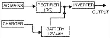
The UPS presently designed is of online type. Here the inverter is ‘on’ throughout irrespective of the presence of the AC mains. When the AC mains is present, the same is converted into DC and fed to the inverter. A part of the mains rectified output is used to charge the battery. When the mains power fails, the DC supply to the inverter is from the battery and from this is obtained AC at the inverter output. This is shown in fig.1.
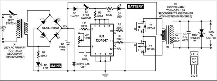
The circuit wired around IC CD4047 is an astable multivibrator operating at a frequency of 50 Hz. The Q and Q outputs of this multivibrator directly drive power MOSFETS IRF540. The configuration used is push-pull type. The inverter output is filtered and the spikes are reduced using MOV (metal oxide varistor). The inverter transformer used is an ordinary 9V-0-9V, 1.5A mains transformer readily available in the market. Two LEDS (D6 and D7) indicate the presence of mains/battery.
The mains supply (when present) is stepped down, rectified and filtered using diodes D1 through D4 and capacitor C1. A part of this supply is also used to charge the battery. In place of a single 12V, 4Ah battery, one may use two 6V, 4Ah batteries (SUNCA or any other suitable brand).
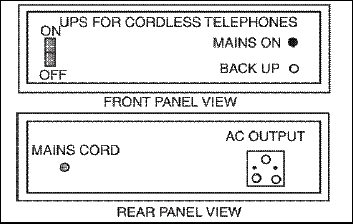
The circuit can be easily assembled on a general-purpose PCB and placed inside a metal box. The two transformers may be mounted on the chassis of the box. Also, the two batteries can be mounted in the box using supporting clamps. The front and back panel designs are shown in the Fig. 3.
The same circuit can deliver up to 100W, provided the inverter transformer and charging transformer are replaced with higher current rating transformers, so that the system can be used for some other applications as well.