


 This resistance meter can measure resistances up to 200 mega-ohms. The value of the resistance is indicated on a linear meter scale (0-100 uA). The operation of the circuit is based on sensing the voltage drop across a reference resistor. The voltage sensing IC used here is a CMOS NAND gate (CD4011) whose high impedance makes it suitable for sensing the voltage drop across high resistances.
Connect the high resistance (Rx) to be measured in series with the reference resistor (here Rref = 10 mega-ohms). Apply a variable high voltage (up to 100V) at the other end of the unknown resistor (Rx) such that the voltage drop across the reference resistor (Rref) is equal to the threshold voltage (Vthr) of gate N3 of IC1.

At this point, the voltage drop across the reference resistor (Rref) is sensed by gate N3 and its output goes low. Gate N4 inverts the low input to light up LED1. Now stop varying the high voltage. The resistance value is indicated on the meter directly.
At this time, the expression for the unknown resistance Rx by applying Ohm’s law can be written as:![]()
where ‘V’ is the voltage applied across the Rx-Rref series combination (i.e, the voltage at the emitter of transistor T4) and Vthr is the threshold voltage of gate N3, which is also the voltage drop across the reference resistor (Rref) when LED1 glows.
From Eq. (1), it is clear that the second term (-Rref) has to disappear in order to have a direct linear relationship between V and Rx. The equation can be rearranged as:![]() This shows that by subtracting Vthr from V, the relationship between V-Vthr and Rx becomes directly linear (without any offset). This subtraction is achieved by using transistor BC557 (T5) as the voltage follower with potmeter VR6. Adjusting the potmeter to get Vthr at the emitter of BC557 produces the required offset voltage at the other end of the meter to nullify the second term (Vthr) such that the current through the meter is proportional to Rx.
This shows that by subtracting Vthr from V, the relationship between V-Vthr and Rx becomes directly linear (without any offset). This subtraction is achieved by using transistor BC557 (T5) as the voltage follower with potmeter VR6. Adjusting the potmeter to get Vthr at the emitter of BC557 produces the required offset voltage at the other end of the meter to nullify the second term (Vthr) such that the current through the meter is proportional to Rx.
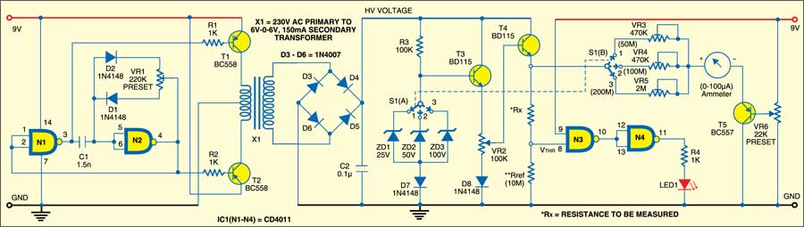
The high-voltage section consists of a high-voltage generator, which is basically an oscillator driven by step-down transformer X1. A 230V AC primary to 6V-0-6V AC, 150mA secondary transformer is used here. To derive the power supply, the transformer output is rectified by a bridge rectifier comprising diodes D3 through D6, filtered by capacitor C2 and regulated by zener diodes ZD1, ZDandZD3 (25V, 50V, 100V) in combination with transistor BD115 (T3). Diodes D7 and D8 (each 1N4148) provide the required additional drop in voltage across the base-emitter junction of transistors T3 and T4 (each BD115).
The transformer can be wound on any ferrite core having dimensions of about 30X10X30 mm3. A primary-to-secondary turn ratio of 25:350 will produce around 100V from 9V. At 100V, the current through a 10-mega-ohm resistor would be 10 A. This means a power requirement of VxI = 100×10-5 = 10-3 watts, which can be easily achieved using an ordinary 9V battery. Most of the power is drawn by the regulating circuit and some by the meter.
Presets VR3, VR4 and VR5 are used for calibration to get full-scale deflection (FSD) in the analogue ammeter. You can directly calibrate VR2 on a dial and use LED1 for indication. The meter has been added for convenience and reliability. It eliminates all ambiguities of any non-linearity associated with variable voltage at the emitter of T4.
