


Efficiency of a solar charging system depends on the weather conditions. Usually the solar panel gets four to five hours of bright sunlight in a day. If the weather is cloudy or rainy, it affects the charging process and the battery does not attain full charge. This simple hybrid solar charger can solve the problem as it can charge the battery using both solar power as well as AC mains supply.
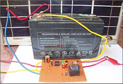
When output from the solar panel is above 12 volts, the battery charges using the solar power. When the output drops below 12 volts, the battery charges through AC mains supply. Fig. 1 shows the author’s prototype.
Solar charger circuit and working
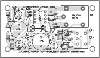
Fig. 2 shows circuit for the hybrid solar charger, which is built around a 12V, 10W solar panel (connected at SP1), operational amplifier CA3130 (IC1), transistor BC547 (T1), 12V single-changeover relay (RL1), step-down transformer X1 and a few other components.

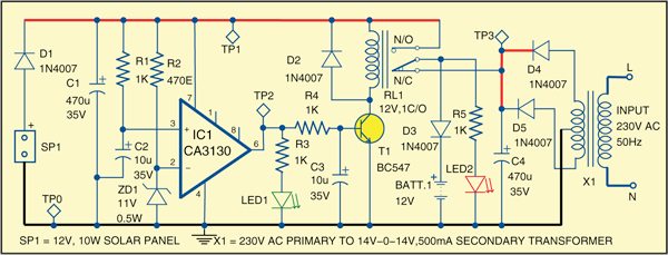
In bright sunlight, the 12V, 10W solar panel provides up to 17 volts DC with 0.6-ampere current. Diode D1 provides reverse polarity protection and capacitor C1 buffers voltage from the solar panel. IC1 is used as a simple voltage comparator. Zener diode ZD1 provides a reference voltage of 11 volts to the inverting input of IC1, while the IC’s non-inverting input gets voltage from the solar panel through R1.
Working of the circuit is simple. When output from the solar panel is 12 volts or more, zener diode ZD1 conducts and provides 11 volts to the inverting terminal of IC1. Since its non-inverting input gets a higher voltage at this time, the output of the comparator turns high and the same is indicated by glowing green LED1. Transistor T1 then conducts and relay RL1 energizes. Thus the battery gets charging current from the solar panel through the normally-open (N/O) and common contacts of relay RL1.
LED2 indicates charging of the battery. Capacitor C3 is provided for clean switching of transistor T1. Diode D2 protects T1 from back EMF and diode D3 prevents the discharge of battery current into the circuit.
When output from the solar panel drops below 12 volts, output of the comparator turns low and the relay de-energizes. Now the battery gets charging current from the transformer-based power supply through the normally-closed (N/C) and common contacts of the relay. This power supply comprises step-down transformer X1, rectifying diodes D4 and D5, and smoothing capacitor C4.
Download PCB and component layout PDFs: click here
Construction and testing
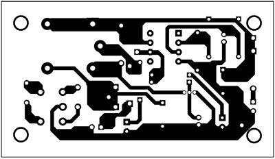
An actual-size, single-side PCB for the hybrid solar charger is shown in Fig. 3 and its component layout in Fig. 4. After assembling the circuit on PCB, enclose it in a suitable box. Use high-gauge (thick) wires to connect the solar panel and the battery to the circuit.
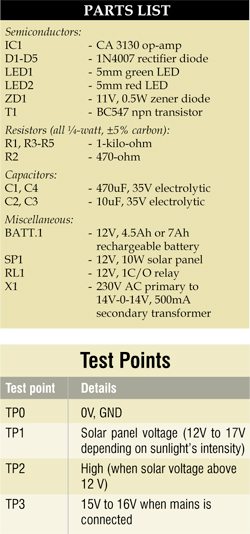
To test the circuit for proper functioning, remove the solar panel from connector SP1 and connect a DC variable voltage source. Set some voltage below 12V and slowly increase it. As the voltage reaches 12V and goes beyond, the logic at test point TP2 changes from low to high. The transformer-based power supply voltage can be checked at test point TP3.

Can I use 20w panel instead of 10w?
Yes, surely you can use 20W solar panel
How much current this circuit can handle?
The circuit will require less than 1 ampere current.
What is the main use of this in modern world
can it work with 60W solar panel?
Yes, it will work if it is rated at 12V
What is the advantage if we are charging the solar cells with the A.C current? It’s just storing the energy and simply acting as common inverters we use in our everyday life.
why the transformer is full time on in all time is it is good., is lt be avoided?
hi i m from nainital can you call me in my no 9359485591
Hi Jitendra Bhatt,
Could you please elaborate your query?
Can I use 5w instead of 10w
Yes, but it will take time to charge
Good Work! But if we want to increase input solar power wattage e.g. 1kW, then how many changes are required in circuit.
Green light LED getting .76 v & relay activated. where is the problem? need each ic pin voltage!!!.
transformer secondary connected across two diodes that direction of diode is correct? if will change any one diode direction what it will happen?
Hi, i have two queries,
1) why the transformer is full time on in all time? Can we turn off transformer supply when it transformer is not in use.
2) This circuit automatically turns ON charging of battery, but can it automatically turn OFF battery charging when battery is full??
are there journal papers writtten on solar hybrid
plz hepl me with this
in which software can we do the simulation of this
@efylab.Can I use my car alternator in place of the solar cell and then connect the hybrid solar charger to it? Will it charge my 100amps battery?
Actually i made this circuit on GPB (general purpose board) , the o/p is approx 17v and also battery is charging ; however,realy is not operate and charging of battery is not automatically stop
This circuit is really working fine but in cloudy condition sometimes relay is chattering rapidly from solar to mains. When light intesity changes from low to high or vice-versa problem disappear and yhe circuit again works accordingly on the intensity of the sunlight. Could you solve me out please.
Thanks for the feedback. For a temporary solution, you can either switch off the circuit or use higher capacitance values
Sir, can anybody call me need ready pcb for this charger.
Wtsap 9356837273
We do not have the PCB right now, however you can easily assemble on a general purpose PCB as shown in author’s prototype(Fig.1)
sir!
would you please tell me where is the output terminal to connect the load for verification
Dear Ragheeb,
As it a charger project. Thus the battery gets charging current from the solar panel through the normally-open (N/O) and common contacts of relay RL1.So there is no need of connecting load,you just connect 12V chargeable battery (BATT.1) which works as a load .