

One of the common method in determining the quality of water is the measurement of Total Dissolved Solids (TDS). TDS meter is a widely used water quality sensor which measures the conductivity of water sample to calculate TDS. The conductance pure water is intrinsically very less; the addition of impurities increases the conductance, which can be calculated from the measured conductivity value. The most commonly used TDS meters uses a lot of external blocks such as Oscillator, Op-amp based non-inverting amplifier, Rectifier etc. PSoC (Programmable System on Chip) gives the advantage of built-in configurable analog and digital blocks, which can be used to build the complete solution with a few external discrete components. A comparison of a few of the existing implementations and the advantages of building a TDS meter using PSoC is presented in this article.
Introduction
Measurement of water quality is one of the important topics in both industrial and commercial applications. One of the direct methods to measure the quality of water is the measurement of TDS in water. There are different methods to measure TDS, of which measuring the conductivity of the water sample is one method which gives moderate to fairly high accuracy.
Conductivity of pure water is very low (approx. 5uS/cm). The addition of impurities increases the conductivity of water. The concentration of impurities can be calculated by measuring the conductivity of water samples. TDS meter is a commonly used instrument which measures the TDS using conductivity method.

In the existing methods, two electrodes are placed in the water sample and a sine wave of known amplitude and frequency is applied to one electrode. The received sine wave at the second electrode is compared with the applied sine wave to calculate the conductance. This circuit includes a Wein bridge oscillator to generate sine wave, an Op-amp based amplifier/comparator to calculate the relative gain (attenuation) of the received signal and an ADC to convert the calculated analog conductance value to digital. An MCU will be required to process/convert the ADC output to required format as well as the interface different user interface components such as Display, buttons etc.
Programmable System on Chip (PSoC) is the combination of MCU and configurable analog and digital blocks. PSoC includes DAC which can be used to generate Sine wave and configurable Op-amps which can be used to build amplifier/ comparator to calculate the relative gain of received signal. The output of the comparator can be fed to the internal ADC which can be read directly by the MCU. The MCU makes necessary calculations to convert the conductance value to TDS value in ppm which can be output to a display.
PSoC includes built-in driver for LED and LCD displays, which can be used to interface a Segment LCD, Graphic LCD or Character LCD for displaying the TDS value. PSoC additionally supports CapSense technology, which can be used to implement buttons, sliders Proximity sensing etc. Another feature available in PSoC is BLE radio with a royalty-free BLE stack which could be helpful in building wireless TDS sensors.
Theory of Operation
As mentioned in the previous section, TDS can be calculated by measuring the conductivity of water sample. Conductivity, the reciprocal of resistance, can be measured directly using an Ohm meter in solids. However, the measurement of conductivity in fluids is not quite as straight forward. Ohm meters (or voltmeters) pass a DC current between two electrodes to measure the resistance. In water, the conductivity is caused by the dissolved salt molecules. DC current injected by the voltmeter or ohm meter will cause these molecules to break down (ionize) and migrate to the electrodes. The conductivity value measured will be keep on varying, thus making the reading useless. This limitation can be overcome by passing an AC current instead of DC current. When the frequency of the AC signal applied is sufficiently large (> 5kHz), the molecules no longer break down, thereby giving a more accurate reading.
The conductivity measured need to be converted to ppm which is the more common unit used for TDS values. The conversion of conductivity to ppm may seem trivial, but in reality, this is not the case. There are many factors which decide the conductivity of water sample such as the type of dissolved solids, the material used for electrodes, the physical dimensions of the electrodes, the spacing between electrodes and so on. To standardize the measurement, the conductivity values (EC) are measured using two probes spaced 1cm apart and the value is expressed in terms of uS/cm. The EC value measured can be converted to ppm by multiplying with a conversion factor, depending on the type of dissolved salts. Since the type of dissolved salt is unknown in most of the cases, the conversion factor of 500 for NaCl is most commonly used in TDS meters. Thus 1 us/cm of conductivity measurement corresponds to 500 ppm of TDS.
Another important factor which affects the conductivity is the temperature of the water sample. The conductivity of water sample increases with temperature since the mobility of molecules or ions increases. It is essential to measure the temperature of water sample and to include temperature compensation in the calculation.
Existing Solutions
One of the most common method used for building TDS meter is using a Wein Bridge oscillator. Wien bridge oscillator is used to generate a Sine wave (AC current) of desired frequency. The sine wave is passed through the water sample and the amplitudes of the injected and received waves are compared to calculate the conductivity.
In the method given in Figure1, the probes are placed in the feedback loop of an Op-amp amplifier. The gain of the Op-amp thus depends on the conductance of the water sample. The output of the Wein bridge oscillator is the input to the amplifier and the probes are immersed in the water sample. The sine wave is indirectly passed through the water sample, which give the advantage of passing a very low current. When the conductance is very low or open, the gain of the amplifier is unity. As the conductance increases the gain of the amplifier increases accordingly. The output of the amplifier is then converted to DC and input to an ADC, the output from which the conductance can be calculated.
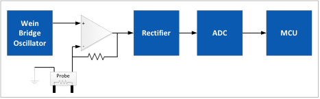
The major disadvantage of this method is the need of a lot of external discrete components. The accuracy of discrete components tends to degrade with aging making the measurement inaccurate. The initial calibration of the circuit is also quite difficult with more external components.
In another method as shown in Figure 2, the conductivity is measured from RC time constant of a parallel RC circuit with a known capacitor value and the unknown resistance value of the water sample. The capacitor is first charged to the supply voltage level of the microcontroller. The probe immersed in water sample is then brought in parallel to the capacitor to discharge the capacitor. The voltage across the capacitor is given as input to a Schmitt trigger to calculate the time to discharge to a known threshold level. The measurement is then repeated by charging the capacitor in opposite polarity to provide the AC effect. The time constant obtained from several measurements are averaged and the conductance is calculated.
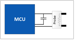
This circuit being very easy to build and implement, there are still a lot of limitations. The capacitor value required varies for the different limits of conductance values. Another limitation would be the accuracy of the capacitor. The input noise margin or the hysteresis of the Schmitt trigger will be another factor contributing to the inaccuracy in the measurements. The noise levels or variations in the supply voltage rail will be another significant factor which can affect the accuracy of the measurement.
Proposed Solution
The major disadvantage observed in the existing implementations is the dependency on a lot of external components including discrete components which affect the accuracy of the measurement. In all the methods, microcontroller is used only for capturing the ADC output. Any variations in the frequency generation circuit or the properties of external discrete components will not get reflected in the MCU. Another limitation is that any parameter in the TDS value which depend on the frequency or amplitude of the excitation wave will not get captured.
As an alternate a fully digital implementation controlled from MCU is proposed. In this method a DAC is used to generate the AC current. The MCU will generate the waveform in digital format which get converted to analog by the DAC. The advantage of this method is that the AC waveform is controlled by MCU, which can vary the frequency or amplitude as required.
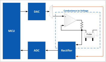
The output of the DAC need to be given to a suitable circuit to convert conductance to voltage which can be read by the ADC. The conductance to voltage conversion can be done in different ways, the preferred one being the one similar to Figure 1 where the conductance probe is introduced to the feedback loop of the Op-amp amplifier. The output of Op-amp will be the input waveform amplified by the ratio of feedback resistor by the resistance of the water sample.
The output of the Op-amp may be directly converted to digital form by ADC and compared with the generated waveform. The limitation with this method is that any momentary variations in the amplitude levels will affect the measurement accuracy significantly. Another major difficulty would be to phase align the transmitted and received waveforms before comparison. To overcome these difficulties, the output of the Op-amp is passed through a rectifier to calculate the RMS value of the received signal. The RMS value of the received signal is then converted to digital value by the ADC. An option to bypass the conductance measurement and feed the DAC output directly to the rectifier is also provided to calculate the RMS value of the transmitted wave. The RMS value of the received wave is compared with the RMS value of the transmitted wave to calculate the conductance value which is then converted to TDS measurement in ppm using a suitable conversion factor.
The advantage of this method is the full control of the measurement by the MCU which provides more accurate readings. The downside of this implementation is again a lot of external components adding to cost and complexity. Implementing this design with the PSoC will do away with these limitations, the reason for selecting the given architecture.
Implementation using PSoC
The PSoC is a combination of MCU and programmable analog and digital blocks. The PSoC 1 and PSoC 3 family are made up of 8bit MCUs and PSoC4 and PSoC5 families are made up of 32 bit MCUs. PSoC devices features flash memory up to 256KB, internal EEPROM up to 2KB and SRAM up to 64KB. The programmable analog blocks include Analog Mux, Op-amps, Comparators, ADC with input buffering, channel sequencer, current DAC (IDAC) etc. Programmable digital blocks are called Universal Digital Blocks (UDB) each with eight macrocells and datapath which can be configured to build a numerous combinational and sequential logics.
The internal MCU, DAC, Analog MUX, Op-amps and ADC of the PSoC can be utilized to build the complete TDS meter along with a few discrete components, thereby significantly reducing the BOM cost and design complexity.
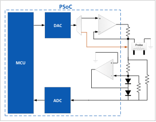
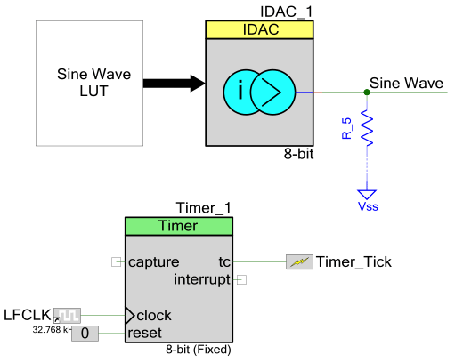
The Wein bridge oscillator used in the common implementation can be easily replaced with sine wave samples stored in a LUT in the flash of the MCU send to the DAC. Please refer the article from Ido Gendel (PSoC 4: The sounds of IDAC) for an easy implementation of Sine wave using PSoC. A sample PSoC creator schematics for the same is given below.
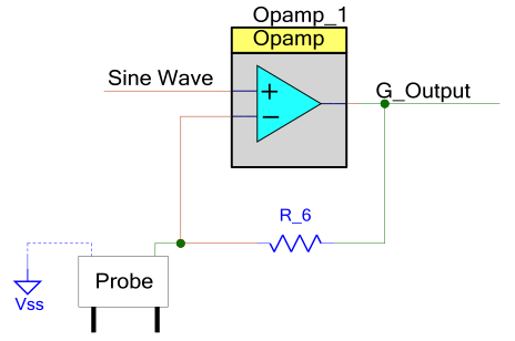
The next stage, conductance to voltage conversion circuit can be implemented using the internal Op-amp of PSoC, an external resistance and the conductance probe as shown in schematics below.
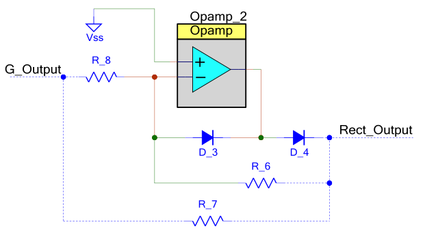
A simple rectifier using diodes would compromise the accuracy of the measurement, an Op-amp based precision rectifier is required. Again the internal Op-amp of the PSoC can be utilized with external two diodes and three resistors.
The output of the rectifier stage is fed to the internal ADC of PSoC. The RMS value of the received signal can be calculated by MCU from the ADC output. An excellent article from Aubrey Kagan may be referred for an easy implementation of RMS measurement using PSoC (Measuring an RMS signal on a PSoC5).
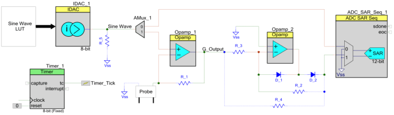
To measure the RMS value of the transmitted signal, the output of the DAC can be bypassed to the rectifier input using the internal Analog MUX. The conductance value can be calculated from the RMS values of the transmitted and received signals and can be converted to TDS value in ppm. The calculated TDS value may be displayed on a character LCD or segment LCD, again for which PSoC Creator components are readily available which reduces the implementation effort. The overall implementation excluding the MCU functions is given in the schematics below.
Additional Benefits of using PSoC
As discussed in the previous section, PSoC provides a completely integrated solution with minimal external components. Apart from this, the most important advantage of using PSoC is the ultra-low power mode, which consumes <1µA current, which makes it an excellent candidate for battery operated devices. This would provide a shelf life of nearly 5 years with a coin cell battery of capacity 50mAh.
Another advantage of PSoC is the capability to drive LED and LCD displays which can be used for displaying TDS values. PSoC has operating range of 1.71V to 5.5V which helps in interfacing with a wide range of external peripherals.
PSoC supports CapSense technology, which helps in implementing buttons sliders etc. on the PCB itself, without the need of any additional mechanical or electrical components. This reduces failure due to mechanical buttons, as well as helps in implementing a fully waterproof solution.
Bluetooth Low Energy (BLE) with royalty free BLE stack is another feature available in some of the PSoC families, which can be used to build wireless TDS sensors. The group of such BLE based TDS sensors may be configured as a BLE mesh and deployed in water treatment plants to periodically measure the water quality at different stages.
Another aspect worth to mention is PSoC Creator. Using PSoC Creator IDE tool all the interface and logic can be designed. The PSoC Creator IDE tool provides a lot of built-in and handy components SARADC, IDAC, Op-amp, Timer, AMUX Display, CapSense (with SmartSense Component) etc. Internal system clock without the need of any external clock/oscillator circuitry is another highlight of PSoC Creator. PSoC Creator provides a lot of features such as integrated compiler tool chains, place and route selected components, interface to production programmers etc.
Conclusion
A comparison of different TDS meter implementations is presented in this article. As an alternate, a digital implementation fully controlled from MCU is proposed in this article. Additionally, the advantages of using PSoC over conventional MCU and external components is compared and highlighted in this article.


Thanks for this useful information.
Is it possible to implement the same solution with a different microcontroller and external OP-Amp. If possible which Op-Amp should I use for the precision rectifier and other amplification purposes.
Hi Author,
The last method seems good, but here is my quaestion, how the TDS reading will not affect with respect to little change in water temperature ( # 10 degree summer to winter), as we all know temp of water is directly proportional to electric conductance of water. Is there any solution adding a thirmister in the circuit.
A help on this would be great.
Regards
Rajiv
[email protected]
Hi Rajiv,
Thermistor can be easily added to PSoC. Please refer to the app note from Cypress – http://www.cypress.com/file/45091/download
Regards,
Avinash
I am a french teacher and I search since a long time to build a low cost conductivity meter for experiments with my student.
I know Arduino quite well and recently I discovered and bought some psoc modules, especially the CY8CKIT-059.
Miraculously, I found your paper and your video on PSoC-Stat.
But…I’m just starting to learn how to use psoc :
– is there a folder with the program ?
– where can I find it ?
thanks
Dear Author,
We would like to build a low cost conductivity meter by using conductivity sensor of LFS-1305 that exciting voltage is 0.7Vpp and measuring frequency 100Hz to 10 kHz. Could you let us know how to write programmable System on Chip (PSoC) is the combination of MCU and configurable analog and digital blocks ? Is it possible to provide layout/ design diagram of PCB with PSoC for Sensor LFS-1305 (maker IST).We will pay for this job.
Hello, i will make a PCB design for the LFS1305 sensor on it that measures conductivity for you if you’d like. Message me on [email protected]
Dear Author,
As per my understanding of generating the AC voltage. We will require the voltage in +/- for example sine wave of output +/- 3V. Because if we generate a positive sine wave then won’t the water molecules ionize. So won’t we require a level shifter after the DAC because all the DAC output are in positive halves that is 0- 3.3 V or 0- 5 V.