


 Most optical interruption counters make use of a light bulb with light-dependent resistor (LDR) or ordinary phototransistor as the sensor. The interruption counter work satisfactorily in darkness only and cannot be used outdoors because of the chances of false counting due to light sensed from other light sources like sun, light bulb, etc.
Infrared interruption counter
The interruption counter described here uses an infrared (IR) sensor that can sense a particular modulated frequency of infrared beam. A small transmitter circuit employing an IR LED is used to emit modulated IR signals.
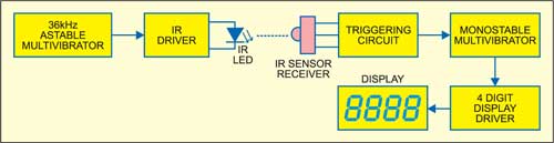
The block diagram of the infrared interruption counter providing an overview of the system is shown in Fig. 1. The astable multivibrator produces 36kHz frequency and npn transistor BC547 drives the IR LED to transmit the modulated infrared signal. The transmitted IR signal continuously falls on the IR sensor (receiver).
When somebody crosses the path of the IR beam falling on the sensor, the triggering circuit activates to trigger the monostable multivibrator. The output of the monostable advances the count of the 4-digit counter-cum-display driver to display the count on 7-segment, common-cathode displays.
Circuit description
The infrared interruption counter circuit consists of power supply, transmitter and infrared interruption counter stages.
Power supply
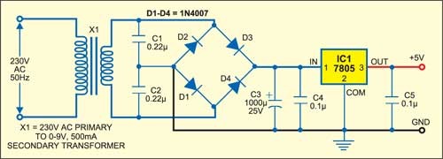
Fig. 2 shows the power supply circuit. The AC mains is stepped down by transformer X1 to deliver secondary output of 9V at 500 mA. The transformer output is rectified by a full-wave bridge rectifier comprising diodes D1 through D4, filtered by capacitors C3 and C4, and regulated by IC 7805 (IC1) to provide regulated 5V supply for the transmitter and infrared receiver-cum-counter stages. Capacitor C5 bypasses any ripple in the regulated output.
Transmitter stage
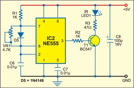
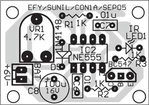
The transmitter circuit (see Fig. 3) works off 5V regulated supply. It is built around timer NE555 (IC2), npn transistor BC547, IR LED1 and some resistors and capacitors.
Timer NE555 is wired as an astable multivibrator whose frequency is set at 36 kHz by adjusting preset VR1. The npn transistor (T1) is used to drive IR LED1, which can transmit modulated IR signals up to around 7 metres without any lense arrangement.
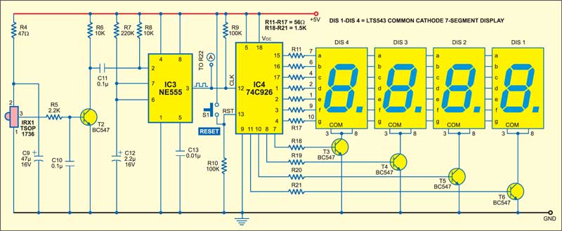
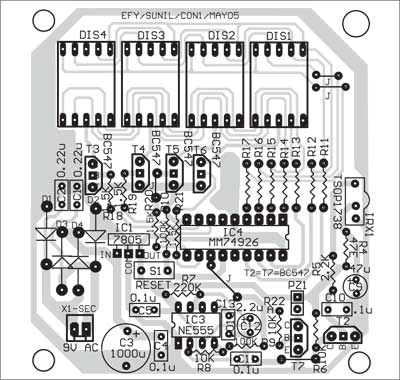
Infrared interruption counter stage. The IR interruption counter circuit (Fig. 4) is built around IR receiver TSOP1736 (IRX1) utilising timer NE555 (IC3), 4-digit counter-cum-display driver IC 74C926 with multiplexed 7-segment output drivers (IC4), 7-segment common-cathode displays DIS1 through DIS4, BC547 npn transistors and some discrete components.
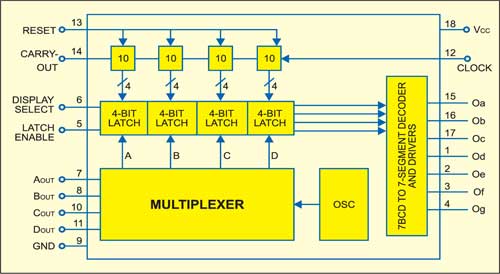
IR sensor TSOP1736 is readily available in the market. It is commonly used in TV sets as a miniaturised receiver for IR remote control systems. Fig. 5 shows the internal functional block diagram and pin configuration of IC 74C926.
IR receiver module TSOP 1736 is meant for pulsed operation. When it is exposed to continuous 36kHz modulated IR beam, its output remains high and the collector of transistor T2 is held low. During a brief interruption of the IR beam, a low-to-high-to-low pulse appears at the collector of transistor T2 to trigger the monostable formed by IC3. The monostable multivibrator is set for a time delay of nearly half second. The 4-digit counter with multiplexed 7-segment output drivers (IC 74C926) advances by one digit for every clock pulse received from the multivibrator. It can count up to ‘9999.’ The counter can be reset to zero at any time by pressing the reset microswitch.
Thus the display, at any time, shows the count of interruption of the IR beam since the last reset. The interruption counter can be employed as visitor counter or object counter in industrial applications.
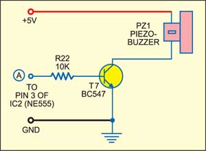
You can add a beeper circuit, as shown in Fig. 6, to provide an audible indication of each interruption. The output pulse from monostable IC3, generated during an interruption, will activate transistor T7 to drive the piezobuzzer for duration of the monostable pulse.
Construction
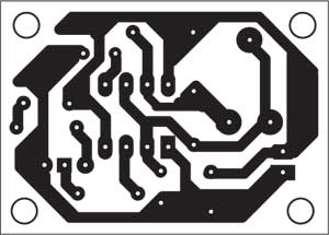
A single-side PCB layout for the IR transmitter (Fig. 3) is shown in Fig. 7 and its components layout in Fig. 8, while the combined PCB layout for the interruption counter (Fig. 4), power supply (Fig. 2) and beeper (Fig. 6) is shown in Fig. 9 with its components layout in Fig. 10.
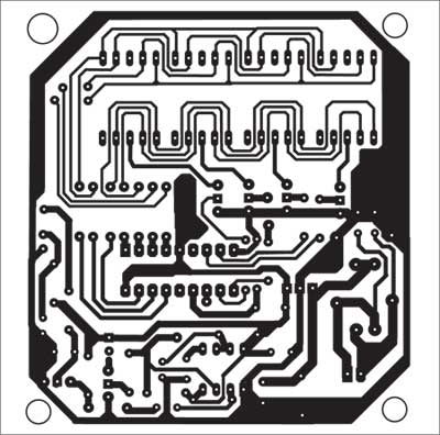
Download PCB and component layout PDFs: click here
For easy servicing, use IC bases to mount the ICs on the PCB. After assembling the PCB, place it near the entry gate. Use long wires for connections to the IR transmitter LED and IR receiver TSOP1736 so that these can be taken out of the PCB and mounted on the opposite pillars of the entry gate. The transmitter should be oriented such that the transmitted IR ray directly falls on the receiver module.
The article was first published in September 2005 and has recently been updated.