


 This infrared object counter can be installed at the entry gate to count the total number of people entering any venue. For example, it can be used at the railway stations or bus stands to count the people arriving per day or week.
The counter uses an infrared transmitter-receiver pair and a simple, low-cost calculator. It works even in the presence of normal light. The maximum detection range is about 10 meters. That means the transmitter and the receiver are to be installed (at the opposite pillars of the gate) not more than 10 meters apart. No focusing lens is required. If an 8-digit calculator is used the counter can count up to 99,999,999 easily, and if a 10-digit calculator is used the counter can count up to 9,999,999,999.
Infrared object counter circuit
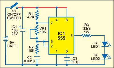
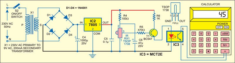
Powered by a 9V battery, the transmitter circuit (see Fig. 1) comprises IC 555 (IC1), which is wired as an astable multivibrator with a centre frequency of about 38 kHz, and two infrared light-emitting diodes (LEDs). The receiver circuit (see Fig. 2) is powered by a 5V regulated power supply built around transformer X1, bridge rectifier comprising diodes D1 through D4 and regulator IC2. It uses an infrared receiver (IR) module (RX1), optocoupler (IC3) and a simple calculator.
Circuit operation
When switch S1 is in ‘on’ position, the transmitter circuit activates to produce a square wave at its output pin 3. The two infrared LEDs (IR LED1 and IR LED2) connected at its output transmit modulated IR beams at the same frequency (38 kHz). The oscillator frequency can be adjusted using preset VR1.
In the receiver circuit, IR receiver module TSOP1738, which is commonly used in colour televisions for sensing the IR signals transmitted from the TV remote, is used as the sensor.
The IR beams transmitted by IR LED1 and LED2 fall on infrared receiver module IR RX1 of the receiver circuit to produce a low output at its pin 2. This keeps transistor T1 in non-conduction mode.
Now when anyone enters through the gate to interrupt the IR beam, the IR receiver module produces a high output pulse at its pin 3. As a result, transistor T1 conducts to activate IC3 and its internal transistor shorts key ‘=’ of the calculator to advance the count by one.
Construction & testing
Both the transmitter and the receiver can be assembled on any general-purpose PCB. Place the transmitter and the receiver around one metre apart.
For calibration, press switches S1 and S2 followed by ‘on’ key of the calculator. Now press ‘1’ and ‘+’ keys sequentially to get ‘1’ on the screen of the calculator. Then, place a piece of cardboard between the transmitter and the receiver to interrupt the IR rays two times. If the calculator counts ‘2,’ the counter is working properly for that range. Repeat this procedure for higher ranges as well. If there is any problem, adjust VR1.
For installation, switch off the transmitter, receiver and calculator, and mount the transmitter and the receiver on the opposite pillars of the main entry gate such that they are properly orientated towards each other. Mount the calculator where you can read it easily. Connect pins 4 and 5 of IC3 across ‘=’ key connections on the PCB of the calculator.
Now switch on the transmitter and the receiver by pressing switches S1 and S2, respectively. Thereafter, switch on the calculator and press ‘1’ followed by ‘+’ key of the calculator to initialise it. Now your counter is ready to count.
The calculator reads ‘1’ after one interruption, ‘2’ after second interruption and so on.

Am having problem with wiring a calculator since it does not have solderable pad , now help and modify the circuit to use cd4033 and 7 segment to display the counting. Thanks
The text states that the receiver voltage is 5V but the circuit diagram shows the transformer as 240V : 9V Which voltage is it?
5V after regolator 7805