Here is a simple but inexpensive inverter for using a small soldering iron (25W, 35W, etc) in the absence of mains supply. It uses eight transistors and a few resistors and capacitors.
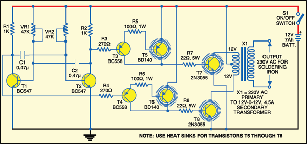
Transistors T1 and T2 (each BC547) form an astable multivibrator that produces 50Hz signal. The complementary outputs from the collectors of transistors T1 and T2 are fed to pnp Darlington driver stages formed by transistor pairs T3-T5 and T4-T6 (utilising BC558 and BD140). The outputs from the drivers are fed to transistors T7 and T8 (each 2N3055) connected for push-pull operation. Use suitable heat-sinks for transistors T5 through T8.
A 230V AC primary to 12V-0-12V, 4.5A secondary transformer (X1) is used. The centre-tapped terminal of the secondary of the transformer is connected to the battery (12V, 7Ah), while the other two terminals of the secondary are connected to the collectors of power transistors T7 and T8, respectively.When you power the circuit using switch S1, transformer X1 produces 230V AC at its primary terminal. This voltage can be used to heat your soldering iron.

Assemble the circuit on a general-purpose PCB and house in a suitable cabinet. Connect the battery and transformer with suitable current-carrying wires. On the front panel of the box, fit power switch S1 and a 3-pin socket for connecting the soldering iron.
Note that the ratings of the battery, transistors T7 and T8, and transformer may vary as these all depend on the load (soldering iron)