
 Need often arises for having an extra telephone ringer in another room to alert you of an incoming call. A low-cost, 2-tone ringer IC LS1240, which is commonly used as part of the telephone circuit, can be wired externally to do the job as long as the telephone line is extended to the place where the extra ringer is to be installed.
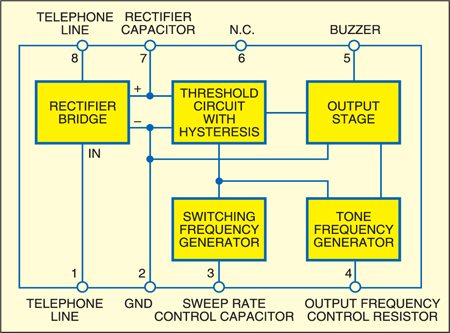
The functional block diagram of LS1240 DIP-8 IC is shown in Fig. 1. It has an inbuilt bridge rectifier-cum-regulator circuit and thus saves you on the component cost. The complete circuit diagram for the external ringer using IC LS1240 (manufactured by Bharat Electronics and STMicroelectronics amongst others) is shown in Fig. 2.
The supply voltage is obtained from the AC ring signal,which is approximately80V AC RMS and regulated inside the IC itself so that noise on the line does not affect correct operation of the IC. The two tone frequencies generated are switched by an internal oscillator in a fast sequence and fed to the output amplifier, which drives the piezobuzzer element directly.

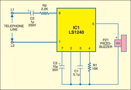
In case you want to replace the piezobuzzer with a loudspeaker, you may do so after adding a 0.1µF capacitor in series with pin 5 of IC1. Both the tone frequencies (f1 and f2) and the switching/sweep frequency (fSWEEP) can be externally adjusted. The value of R1 for a desired frequency f1 and values of tone frequency f2 and sweep frequency fSWEEP can be found using the following relationships:
where abbreviation ‘ln’ stands fornatural logarithm.

With the given values of components, f1≈2 kHz, f2≈1.5 kHz and fSWEEP ≈9.5 Hz.