


 This simple mains box heat monitor circuit monitors the mains distribution box constantly and sounds an alarm when it senses a high temperature due to overheating, helping to prevent disasters caused by any sparking in the mains box due to short circuits. It also automatically switches on a bright white LED when the power fails. The LED gives ample light to check the mains box wiring or fuses in darkness. The circuit beeps once when power fails and again when power resumes.
Mains Box Heat Monitor Circuit
The AC mains is stepped down by transformer X1 to deliver a secondary output of 9V AC at 500 mA. The transformer output is rectified by diodes D1 through D4. Capacitor C1 bypasses the ripple. LED1 indicates the power-on condition. Resistor R1 acts as the current limiter for LED1.
Germanium diode D5 (1N34) is the temperature sensing element, which is connected in the reverse bias mode. At normal temperature, the resistance of the diode is high and, as a result, transistor T1 conducts to hold reset pin 4 of IC1 in low state.

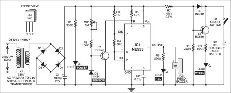
NE555 (IC1) is wired as an astable multivibrator. When the temperature around diode D5 rises due to overheating of the fuse, the resistance of the diode decreases and transistor T1 stops conducting. This enables IC1 and the oscillator starts to sound an alarm. By adjusting preset VR1, you can set the temperature level at which the alarm circuit is activated.
The emergency light circuit uses pnp transistor BC558 (T2) and a few passive components. It is powered by a 9V rechargeable battery, which is constantly charged via forward-biased diode D6 when mains power is present. Resistor R7 reduces the charging current to a safer level. The forward biasing of diode D6 results in reverse biasing of transistor T2 and thus the white LED (LED3) is off. When the power fails, transistor T2 is forward biased and lights up the LED. When the power resumes, transistor T2 stops conducting and the LED doesn’t glow.
Construction & testing
The circuit can be easily constructed on any general-purpose PCB. Diode D5 should be placed close to the fuse to sense the heat. It can be connected to the PCB using a short piece of shielded wire. The white LED should be directed towards the fuse such that the maximum light falls on the fuse.
To test the circuit, take the hot tip of the soldering iron near diode D5. The buzzer will sound to indicate the high temperature.
The article was first published in August 2004 and has recently been updated.

great for new Ideas