 Ozone is a triatomic form of oxygen that is highly unstable and as such cannot be stored. It finds various applications in our daily life. For instance, it is used to detoxicate fruits and vegetables, disinfect wounds, remove bad odour, sterilise containers and clothes, and so on. Therefore a multifunction ozone generator circuit is presented here.
This multifunction ozone generator circuit (shown in Fig. 1) is built around a 14-stage ripple-carry binary counter/divider and oscillator IC CD4060 (IC2), a hex Schmitt trigger IC CD40106 (IC3), transformer (X1), bridge rectifier (BR1), 12V regulator 7812 (IC1) and some discrete components. The circuit can be divided into three sections: power supply, timer and oscillator.
To derive the power supply for the circuit, the 230V AC mains supply is stepped down by transformer X1 to deliver the secondary output of 12V, 1A. The transformer output is rectified by full-wave bridge rectifier BR1, filtered by capacitors C1 and C2, and regulated by IC1. In the absence of mains power supply, the circuit can also be powered by a 12V battery using switch S2.

The timer section is designed around IC2. The values of resistor R1, preset VR1 and capacitor C4 are chosen such that when switch S1 is pressed, Q6 goes high after 2.5 minutes, Q7 after 5 minutes, Q8 after 10 minutes and Q9 after 20 minutes. All the outputs of IC2 are fed to rotary switch S3.
With the help of switch S3 you can set the time for which you want to enable the oscillation section.
Positions 1, 2, 3 and 4 are used for setting the time to 2.5, 5, 10 and 20 minutes, respectively.
The oscillator section is built around IC3. Gate N1 is a square-wave oscillator with adjustable frequency from 100 Hz to 200 Hz. Gates N2 through N6 are connected in parallel to boost current. The strengthened signal is now fed to an n-channel MOSFET (T2), which acts as a switch. T2 is switched at the rate of 150 Hz, producing a high voltage at the high-tension (HT) terminal of the ignition coil. The high voltage difference between the HT terminal and the body of the coil produces spark in the air gap to ionise the air. Ozone ions are generated at the tip of HT terminal. The ignition coil used here is the same as used in two wheelers.
Working of the circuit is simple. Suppose you want to generate ozone for 2.5 minutes. Keep rotary switch S3 at position 1 and turn on switch S1. The relay remains de-energised and the oscillator starts oscillating. The ignition coil starts to produce the spark in the air ionising the oxygen to ozone. The timer energises the relay, disconnecting 12V supply to the oscillator circuit after 2.5 minutes.
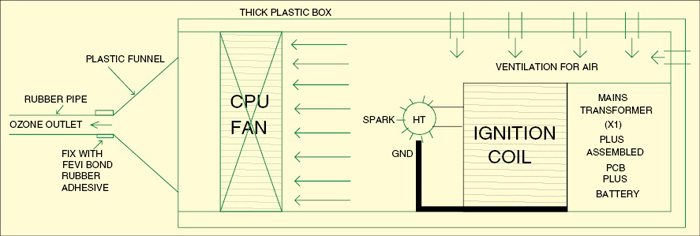
Enclosure similar to the one shown in Fig. 2 can be used. Assemble the circuit on a general-purpose PCB and enclose in an airtight container. Mount switches S1, S2 and S3 at the front side along with LED1. Fit the plastic funnel and CPU fan inside the cabinet as shown in Fig. 2. Fix a 1m pipe to the funnel output for the ozone outlet. Keep the 12V battery inside the cabinet.

Normally, a thick high-voltage cable with metal strip is used in the ignition coil to extend connection for the actual application. The metal strip should be brought about one centimetre close to the body of the ignition coil so as to ionise the air between them. The closed container should have openings to allow the air inside. A small air pump used in aquariums or CPU fan can be used to push ozone ions out and suck normal air into the cabinet.
EFY warning. Care should be taken while handling the ignition coil to avoid the risk of shock. It is dangerous to touch HT part of the circuit because it produces a high voltage in kV range. Exposure to ozone for more than 5 minutes is harmful.


Will you provide pcb and ozone tube .
Regards
Swaran Singh