


 Here is a circuit that stimulates nerves of that part of your body where electrodes are attached. It is useful to relieve headache and muscular pain and revive frozen muscles that impair movement. Though it provides muscles stimulation and invigoration, it’s mainly an aid in removing cellulitis. The system comprises two units: muscular stimulator and timer. Fig. 1 shows the circuit of the muscular stimulator.
Muscular stimulator circuit
IC 7555 is wired as an astable multivibrator to generate about 80Hz pulses. The output of IC1 is fed to transistor T1, whose emitter is further connected to the base of transistor T2 through R3 and VR1. The collector of transistor T2 is connected to one end of the secondary winding of transformer X1. The other end of the secondary winding of the transformer is connected to ground.
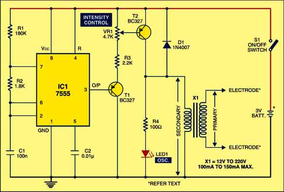
Circuit operation
When IC1 oscillates, transformer X1 is driven by the pulse frequencies generated to produce high voltage at its primary terminals. Separate electrodes are connected to each end of the primary winding of transformer X1. Diode 1N4007 (D1) protects transistor T2 against high-voltage pulses generated by the transformer.

Using potentiometer VR1 you can control the intensity of current sensing at the electrodes. The brightness level of LED1 indicates the amplitude of the pulses. If you want to increase the intensity level, replace the 1.8-kilo-ohm resistor with 5.6 kilo-ohms or higher value up to 10 kilo-ohms.
X1 is a small mains transformer with 220V primary to 12V, 100/150mA secondary. It must be reverse connected, i.e., connect the secondary winding to the collector of T2 and ground, and primary winding to the output electrodes. The output voltage is about 60V but the output current is so small that there is no threat of electric shock.

Electrodes are made of small, thin-gauge metallic plates measuring about 2.5×2.5 cm2 in size. Use flexible wires to solder electrodes and connect to the output of the device. Before attaching metal electrodes to the body, wipe them with a damp cloth. After attaching the electrodes to the body (with the help of elastic bands on Velcro straps), flip switch S1 to activate the circuit and rotate the knob of intensity-Control preset VR1 very slowly until you feel a slight tingling sensation.
Timer circuit
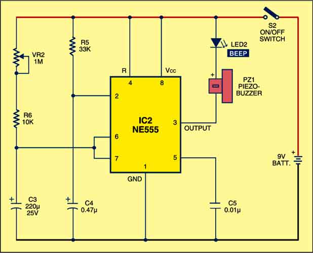
Fig. 2 shows the timer circuit. It uses IC NE555 wired in monostable mode. Initially, when you press switch S2, the monostable triggers and its output goes high for 10 minutes. Thereafter, its output goes low to give a beep sound from the piezobuzzer and lights up the red LED (LED2) indicating that stimulation time is over.
Construction & testing
Assemble the timer with a separate switch and a 9V DC battery in the same cabinet as the stimulator. Tape the electrodes to the skin at opposite ends of the chosen muscle and rotate VR1 knob slowly until you sense light itching when the muscular stimulation circuit is powered on. At the same time, flip switch S2 to start the timer for counting the time. At the end of the timing cycle, the piezobuzzer beeps. Each session should last about 10 minutes.
Caution
Heart patients and pregnant women should not use this device. Also, do not attach electrodes to burns, cuts, wounds or any injury. Consult your physician before using this circuit.
The article was first published in October 2008 and has recently been updated.


if i want to display the intensity level of the led on a micro controller , where should i do the connection of the micro controller and the electronic muscle stimulator circuit?
Hi. You can make the micro controller control VR1 and VR2 in the stimulator and also you can make micro controller start to count and display time as S2 switch (in the timer circuit) is turned on. ( I just imagined this feature now, not implemented yet). I wish to use this for another purpose ( my experiment on artificial muscle stimulation).
Hi,
Here i have one question. How are both above ckts connected with each other. I feel timer ckt is independent of stimulator ckt. I was not able to complete this. can you help me?
I am a final year M.sc physics student .pls suggest me some pictures easy projects.if it was any biomedical instrument like muscle stimulator pls suggest me .thank you
Hi
I am getting fluctuating AC voltage ( 0.1 to 3.2 volts).
I want to get a stable AC voltage in the same range (0 to 2 volts).
Any ideas
Why my circuit is not working ? The voltage is not stepping up .. whenever I am giving 12 v I am not getting 220v .. should we use voltage doubler ? What is the specifications of the transformer ? Is all the important information provided there ?
You can simply take the output from the pin three of the monostable configuration and connect it to the +ve rail of the astable multivibrator circuit. It would directly time the output. Instead of using a buzzer to know when to switch the stimulation off.