


 This circuit can measure currents down into the nano-ampere range. It is useful when building, testing and experimenting with low-power circuits, especially those operating off batteries.
The circuit is built around commonly available JFET input op-amp TL081 and a few precision resistors. It has a wide operating range from 0-10 nA to 0-1 A in steps of multiplicative decades. the range can be easily extended to 10 A and 100 A by including additional range resistors of 100 ohms and 10 ohms, respectively.
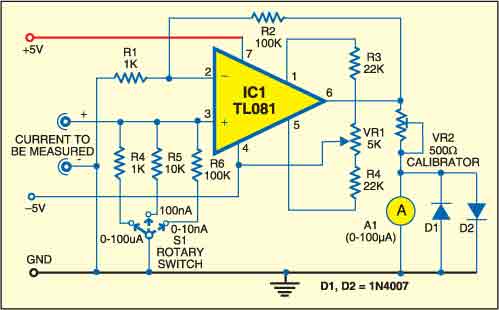
The +\-5V supply (not shown in the circuit) may be obtained from standard 7805 and 7905 regulators to power the circuit. IC TL081 is wired as a high-gain non-inverting DC amplifier with a gain of Rf /R1+1=100. The current to be measured is passed through a fixed known resistor. The voltage drop across this resistor is applied to the amplifier and output as 100xImxR (where Im is the current to be measured). The range can be controlled by selecting R (1 kohms, 10 kohms and 100 kohms) appropriately.

The diode in parallel with the meter protects the circuit against high currents that may occur due to improper range selection. Further, the range resistors do not have any noticeable effect on the current to be measured. For instance, to produce a current of 10 nA from a 5V source, it is necessary to include a 500-mega-ohm resistor in the circuit. Since a 100k ohms is being used to sample this current, it is very small as compared to the large value 500M ohm.
Any meter can be used to calibrate the output, provided the gain of the DC amplifier is changed appropriately. That is, a meter with full-scale deflection of 150A would require a gain of 150 and vice-versa. Using a commonly available digital multimeter, adjust the calibrator (preset VR2) such that the resistance of the calibrator and 100 A meter (typically, which has a resistance of 700 ohms) in series is exactly 1 kilo-ohm. Now wire the entire circuit and adjust the set-zero trimpot to get zero deflection in any range of the multimeter. Now the nano-ampere meter is ready for use.
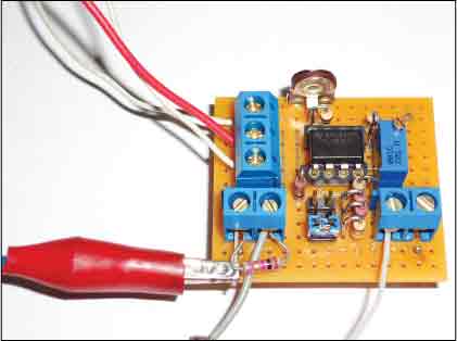
Assemble the circuit on a general-purpose PCB and enclose in a small cabinet. fix the ammeter on the front panel. Provide three terminals for the power supply (-5V, +5V and GND) on the rear panel and two terminals on the front panel for the current to be measured.

Hi , I have a question from you ,
What is the role of ammeter 1 in the circuit?
Arduino source code please.
E-mail : [email protected]
HI Gwak, this Project doesn’t require a source code.
Hi , I have a question from you ,
What is the role of ammeter 1 in the circuit?
cicuit being cost effective doubt it to be off use while testing DC current leakage from heavy duty batteries ( 12VDC,80/180 AH) just like in cars or vehicles
Kindly elaborate your query.