


 Often, at night, a speeding vehicle rams into another vehicle parked at the edge of a highway. Cars have parking flashers, but trucks, buses and loading rickshaws rarely have any form of a warning flasher. Here is a simple Parked-Vehicle Highway Flasher circuit of an effective flasher which is visible from a distance of up to 300 metres.
This circuit is built around a two-input NAND Schmitt trigger CD4093 (IC1), decade counter CD4017 (IC2) and a few discrete components. Two-input NAND gate N1 of IC1 forms an oscillator generating 3Hz clock pulses. These pulses are fed to the clock input (pin 14) of IC2. IC2 has ten outputs Q0 through Q9. Only Q0, Q2, Q4, Q5, Q7 and Q9 are used here. These outputs of IC2 are fed to the bases of respective transistors as shown in the diagram.
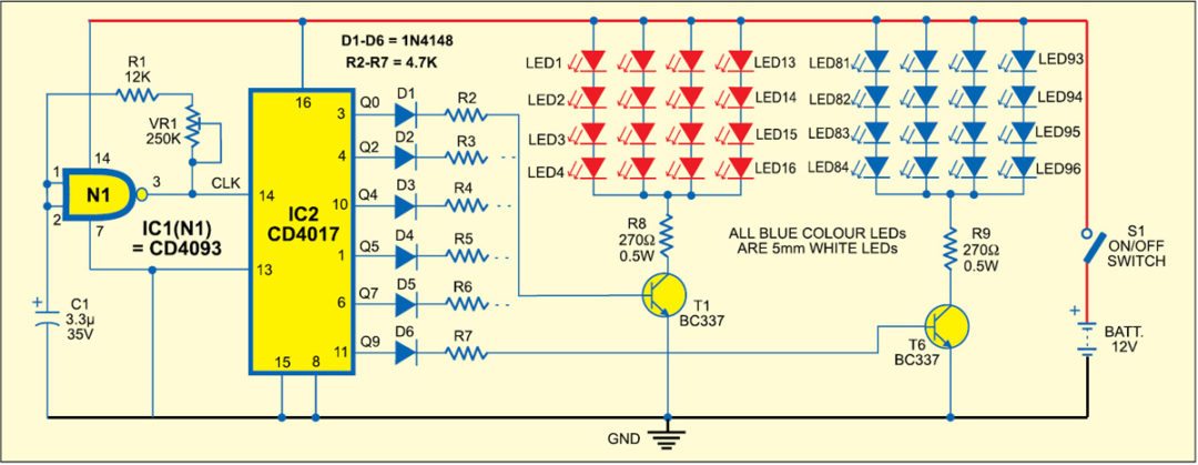
The collectors of transistors are connected to separate LED clusters of 16 LEDs each. These LEDs should be 5mm, clear-lens, high-brightness, and red or white in colour. Here six groups of white and red LEDs are used for the six outputs of IC2. These LED clusters are arranged one after another, which means that collectors of transistors T1, T3 and T5 are connected to red LEDs and collectors of transistors T2, T4 and T6 are connected to white LEDs.

Assemble the circuit on a general-purpose PCB and enclose in a suitable small cabinet. The LEDs can be housed in either square or rectangular automobile cabinets along with white lens. As the circuit consumes very little current, it will not drain the vehicle battery significantly.
You may also like: click here